Network communication setup, Mounting, Elated settings. see the flowchart in – Extron Electronics IPCP Pro Series Setup Guide User Manual
Page 2: Ipcp pro series • setup guide (continued)
2
IPCP Pro Series • Setup Guide (Continued)
Configure the Control Processor and Touchpanels
The most basic steps are outlined below in the recommended order.
NOTE: See the Global Configurator Help file and GUI Designer Help file as needed for step-by-step instructions and detailed
information. The help file for GC includes an introduction to the software and how to start a project and configuration.
If Touchlink Pro touchpanels will be part of the system, start and use GUI Designer to
design, save, and build the graphical
user interface (GUI) layout for the touchpanels. See the GUI Designer Help file for instructions.
Using GC,
create a new GC Pro or GC Plus project and configure the control processor and other IP Link Pro devices.
The configuration tells the control processor how its ports will function; how to control other products; which touchpanels to
interact with; what to monitor; when to do things; and whom to notify, how, and under what circumstances.
Configure ports on the control processor.
•
Select device drivers and link them to each serial, IR/serial, or Ethernet port.
•
Select settings (serial protocol, relay behavior, digital I/O or flex I/O settings) as needed.
Set up monitors, schedules, macros, and local variables.
Add touchpanels and set them up:
•
Upload the GUI configuration to the touchpanels using Global Configurator.
•
Assign any appropriate functions, monitors, or schedules to the touchpanels and their buttons.
Save and build the project.
Upload the system configuration to the control processor.
Test and Troubleshoot
Test the system. See the IPCP Pro User Guide for an outline
of the system testing procedure.
Make adjustments to wiring or configuration as needed.
Network Communication
Setup
Network setup is essential prior to
configuration. Use the flowchart as a
guide to setting up the control
processor for network use.
and Program
Reserve this text for use once eBUS ports are functional, etc.
Add eBUS endpoint devices and set them up:
•
Ensure that the hardware address set on each
endpoint is distinct and matches the addresses
used in the configuration.
•
Assign button functions as desired.
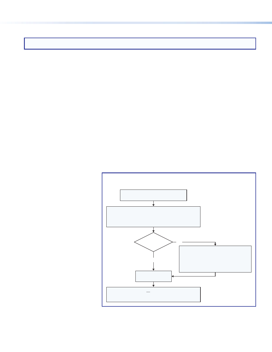
Connect the control processor and PC
to the same LAN and apply power.
Open the Toolbelt utility in
Global Configurator (GC Professional or GC Plus mode).
ToolBelt displays a list of all IP Link Pro devices
connected to the network.
Select the desired
device from the list.
Activate the Identify Hardware feature.
To determine the correct device, click on a
device in the list and observe the device. The
front panel LEDs of the selected device flash.
Click on devices in the list until the LEDs
of the correct device flash.
Do you
know the MAC
address?
Yes
No
Network Communication Setup,
Connected/Online Method
Enable DHCP or you must type in the
IP address, subnet address, and gateway,
then configure other network settings as needed.
Figure 1.
Network Setup, Online Method
Mounting
Securely mount the control processor and other devices and attach cables using the wiring section (
page 5) as a wiring guide. Optional 1U rack shelves and furniture mounting bracket kits are available for use with the
control processor. Read the instructions and UL guidelines that come with the rack shelf or mounting kit for installation procedures.
See the product-specific page at
ol processor.