Introduction, Removing the hsa from the table, Removing the front panel connector – Extron Electronics RJ-11 User Manual
Page 5
RJ-45 to RJ-11 Conversion Kit • HSA 400, 402, 452 Installation
HSA 400, 402, 452 Installation
RJ-45 to RJ-11 Conversion Kit • HSA 400, 402, 452 Installation
Introduction
The Extron HSA 400, HSA 402, and HSA 452 ship with Category
(CAT) 6 cables terminated with RJ-45 connectors between the
front panel and lower enclosure bezel plug-ins. Some users
prefer a telephone (RJ-11) connector. This conversion kit
consists of a length of telephone cable terminated with RJ-11
connectors to replace one of the CAT 6/RJ-45 cables.
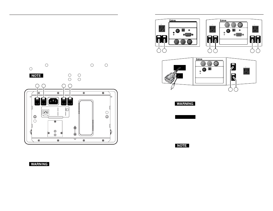
Figure 1-1 shows the location of the bezel plug-ins on the
underside of the lower enclosure for the HSA 402. Figure 1-2
shows the associated connectors on the front panels of the
HSAs. When replacing the CAT 6 cable, match the front panel
connection
A
with the underside connector
A
, match
B
with
B
, and so forth.
Only connectors
A
and
B
are present on the HSA 400.
Only connectors
C
and
D
are present on the HSA 452.
Extron Electronics, Europe
Extron Electronics, Asia
1230 South Lewis Street
Anaheim, CA 92805
USA
714.491.1500
Fa
x 714.491.1517
Beeldschermw
eg 6C
3821 AH Amersfoor
t
The Netherlands
+31.33.453.4040
Fa
x +31.33.453.4050
33-673-01 A
08 01
Printed in the USA
135 Joo Seng Road, #04-01
PM Industrial Building,
Singapore 368363
+65.383.4400
Fa
x +65.383.4664
Extron Electronics, USA
Extron Electronics, Japan
Daisan DMJ Bldg. 6F
3-9-1 Kudan Minami
Chiyoda-ku,
T oky
o 102-0074 Japan
+81.3.3511.7655
Fax +81.3.3511.7656
www.extron.com
HSA 400/402/800/802
AC
125V 10A
50/60 Hz
A
B
C
D
Figure 1-1 — Lower enclosure underside features
Removing the HSA from the Table
Ensure that AC power is disconnected before
servicing the HSA unit.
1
.
On the underside of the clamshell and in the enclosure, cut
the tie wraps that route the AAP cables out of the way.
2
.
Disconnect the IEC power cord and the RJ-45 connectors
from the underside of the surface mount enclosure.
3
.
Disconnect any cables connected to the existing AAPs at
the ends of the cables away from the HSA.
1-2
HSA 400
HSA 400
HSA 402
HSA 452
120-240 50/60 Hz 5A
H. SHIFT
COMPUTER
INPUT
SELECT
AUDIO
RGB 580
xi SI AAP
A
B
HSA 402
H. SHIFT
COMPUTER
INPUT
SELECT
AUDIO
RGB 580
xi SI AAP
120-240 50/60 Hz 5A
120-240 50/60 Hz 5A
A
B
C
D
HSA 452
H. SHIFT
COMPUTER
INPUT
SELECT
AUDIO
RGB 580
xi SI AAP
120-240 50/60 Hz 5A
C
D
Figure 1-2 — Front panel RJ-45 connectors
The edges of the top panel are sharp. Exercise care
when the HSA is removed from the table to prevent
personal injury.
CAUTION
The edges of the top panel are bevelled to an ultra-
fine thickness of less than 0.04 (4/100)”
(approximately 1 mm). These edges are soft and can
be easily nicked or bent. Exercise caution when
handling and mounting the enclosure.
Mishandling can damage the appearance of the
enclosure.
The surfaces of the HSA enclosure have screws and other
protrusions that could damage fine furniture. Do not
rest the enclosure on unprotected furniture.
4
.
On the underside of the table, remove the two bolts that
secure the clamshell to the HSA (figure 1-3). Lift the
enclosure out of the table. Ensure that the cables
connected to the AAPs do not snag or pull on any
protrusions.
Removing the Front Panel Connector
1
Through the access hole in the rear of the enclosure, cut
the tie wraps that bundle the power and CAT 6 cables.
1-3