Reassembling the hsa, Routing the aap cables – Extron Electronics RJ-11 User Manual
Page 12
RJ-45 to RJ-11 Conversion Kit • HSA 800, 802 Installation
RJ-45 to RJ-11 Conversion Kit • HSA 800, 802 Installation
HSA 800, 802 Installation, cont’d
2-6
6
.
Route the conversion kit telephone cable in the same
fashion as the removed CAT 6 cable.
7
.
Snap the replacement RJ-11 connectors on the conversion
kit cable onto the interior of the front panel and lower
frame bezel plug-ins.
Reassembling the HSA
1
.
Use tie wraps to bundle the CAT 6 and telephone cables
(figure 2-4). Use the impressions on the remaining CAT 6
cable of the tie wraps that you cut in Replacing the
connectors, step 2 on page 2-5 as a guide for placing the tie
wraps.
Tie Wrap
Tie Wrap
Tie Wrap
Figure 2-4 — Bundling interior cables
2
.
Rest the front panels in place in the enclosure. Do not
secure the panels in place at this time.
3
.
Open and close the top panel while you experiment with
the routing of the cable bundle. Find a routing that allows
the top panel to open and close smoothly. If desired, use
tie wraps to secure the bundled cables to the tie-down
holes in the lower enclosure or on the mounting frame.
4
.
Secure the two shroud halves to the enclosure frame with
the eight screws (four per side) removed in Replacing the
Connectors, step 1 on page 2-5.
5
.
Replace the front panels in the surface mount enclosure
and secure them in place with the screws removed in
Removing the HSA from the Table, step 5 on page 2-4.
2-7
6
.
Feed the cables connected to the AAPs in the HSA through
the hole in the table and connect them to the devices that
you disconnected them from in Removing the HSA from the
Table, step 3 on page 2-3.
7
.
Carefully lower the HSA enclosure into the table opening.
From the underside, bolt the clamshell to the enclosure
with the two bolts removed in Removing the HSA from the
Table, step 4 on page 2-3.
8
.
Connect the IEC power cord, the RJ-11, and RJ-45 cables to
the connectors on the underside of the surface mount
enclosure.
9
.
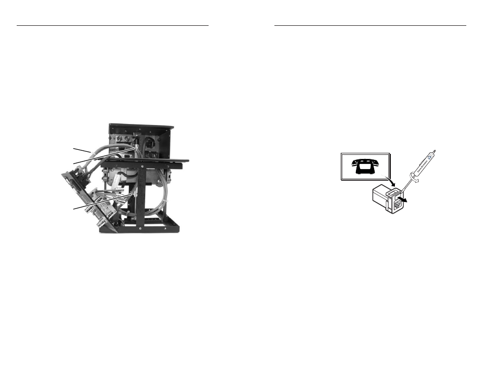
If desired, on the front panel, replace the connector icon by
prying the old icon off of the bezel plug-in (figure 2-5)
with a tweeker and snapping a new icon in place. If
needed, four spare screws are stored in the underside of
the enclosure.
Icon Labels
Figure 2-5 — Changing the connector icon
10
.
Open and close the top panel to check that the cables do
not interfere with smooth operation or rub against sharp
edges. If necessary, reach the cables through the cable
access holed in the lower frame and experiment with the
routing of the cable bundles. If desired, secure the cable
bundles on the mounting frame with tie wraps.
Routing the AAP Cables
1
.
Open the top panel to extend the AAP cables to their
maximum pull.
2
.
Experiment with AAP cable positioning to ensure that the
cables do not rub against the edges of the AAP cable hole
and to ensure that the cable pull does not restrict the
movement of the top panel. Figure 2-6 shows the cables
routed to the side, which proved effective in tests at
Extron.