Rear panel, Front panel, Ea b c d – Extron Electronics DTP T UWP 232_332 D User Guide User Manual
Page 15
DTP T HWP/UWP 232/332 D Transmitters • Installation and Operation
9
Rear Panel
R
DTP OUT
REMO
TE
O
VER
DTP
SIG
LIN
K
RS-232
CONT
AC
T
Tx Rx
Tx Rx
G
PO
WE
R
12V
A MA
X
0.9
+–
G1
2
A/
S
DTP T HWP/UWP 232/332 D
Rear Panel
E
A
B
C
D
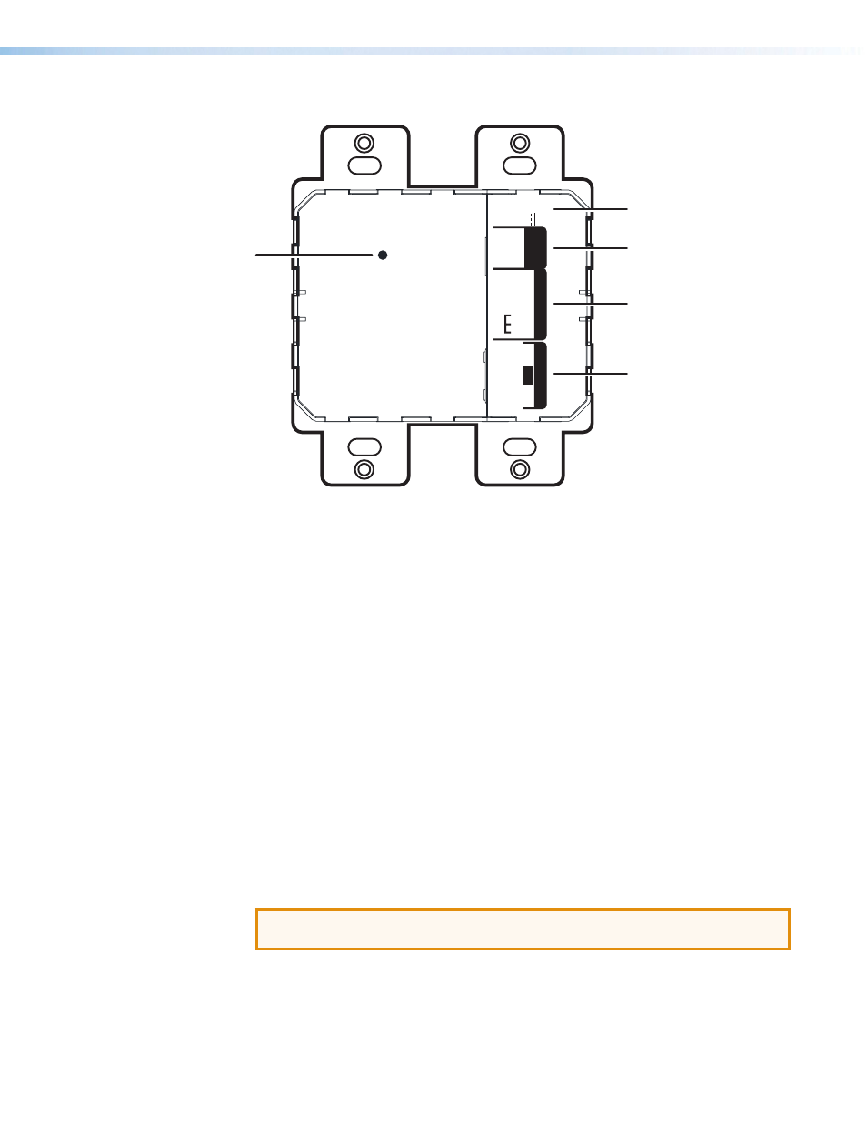
Figure 6.
DTP T HWP 232 and 332 D Rear Panel Connectors
A
DC power input connector — Plug the included external 12 VDC power supply into
either this 2-pole connector (see
on page 13 to wire the power
connector) or the power input connector on the receiver (see the user guide of your
respective receiver for more information).
B
Over DTP control port — Connect an RS-232 device to this 3-pole, 3.5 mm captive
screw connector for pass-through RS-232 control (see
on page 14 to properly wire the RS-232 connector).
C
Remote (RS-232 and contact closure) control port — Connect an RS-232 device,
contact closure device, or both to this 5-pole, 3.5 mm captive screw connector to
control switching on the unit (see
RS-232 and IR Connector Wiring
properly wire the Remote connector).
•
RS-232 — To control the unit through this port, connect an RS-232 device and
configure it as follows: 9600 baud rate, 8 data bits, 1 stop bit, no parity.
•
Contact — Momentarily short pins 1 or 2 to ground (G) to select the corresponding
input. Connect pins 1
and 2 to ground (G) to set the unit to auto switch mode. The
device will select the highest active input.
D
DTP Out port — Connect one end of the twisted pair cable to the RJ-45 connector
on the transmitter (see
TP Cable Termination and Recommendations
to properly wire the RJ-45 connectors). Connect the opposite end of the cable to the
appropriate receiver.
ATTENTION: Do not connect this device to a telecommunications or computer
data network.
E
Reset button — Use an Extron Tweeker or small screwdriver to press and hold the
recessed button for 6 seconds while the extender is running to perform a factory reset.