Making connections, Hdmi connector – Extron Electronics FOXBOX SR HDMI User Guide User Manual
Page 13
Making Connections
HDMI connector
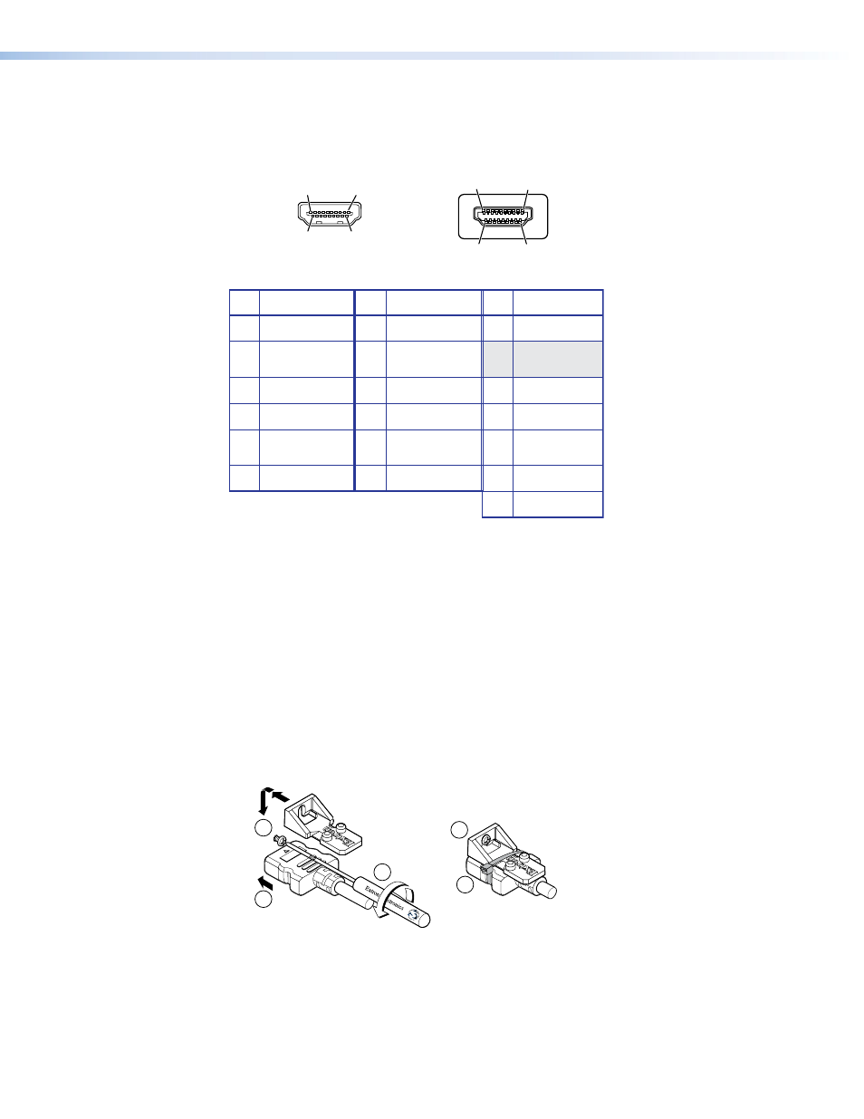
Figure 5 defines the HDMI pin assignments.
Pin
Signal
1
TMDS data 2+
TMDS data 2-
TMDS data 0–
TMDS clock-
+5 V power
Hot plug detect
CEC control
Reserved
(NC)
TMDS data 1+
TMDS clock+
TMDS clock
shield
SDA
DDC / CEC
Ground
TMDS data 2
shield
Pin
Pin
Signal
Signal
2
7
13
4
10
16
11
17
12
18
19
14
3
TMDS data 0-
TMDS data 0
shield
8
9
SCL
15
TMDS data 1-
TMDS data 1
shield
5
6
HDMI
HDMI
Type A Receptacle
Type A Plug
1
18
2
19
1
18
2
19
Figure 5.
HDMI Connectors
HDMI signals run at a very high frequency and are especially prone to errors caused by bad
video connections, too many adapters, or excessive cable length. To avoid the loss of an
image or jitter, follow these guidelines:
•
Do not exceed 16.4 feet (5 meters) on the input of the transmitter or the output of the
FOXBOX SR HDMI scaling receiver.
•
Use only the cable designed for HDMI signals that is supplied by Extron.
•
Limit or avoid the use of adapters.
•
Use only cables specifically intended for HDMI or DVI signals. Use of non-HDMI or
non-DVI cables or modified cables can result in a missing video output.
To securely fasten an HDMI cable to a device:
1.
Plug the HDMI cable into the panel connection (see
a
in figure 6).
3
3
1
2
4
5
Figure 6.
Installing the LockIt Lacing Bracket
2.
Loosen the HDMI connection mounting screw from the panel enough to allow the
LockIt lacing bracket to be placed over it (
b
). The screw does not have to be removed.
FOXBOX SR HDMI • Installation
7