Installation, Rear panel features – Extron Electronics FOXBOX SR HDMI User Guide User Manual
Page 10
Installation
This sections details the installation of the FOXBOX SR HDMI, including:
•
•
Front Panel Configuration Port
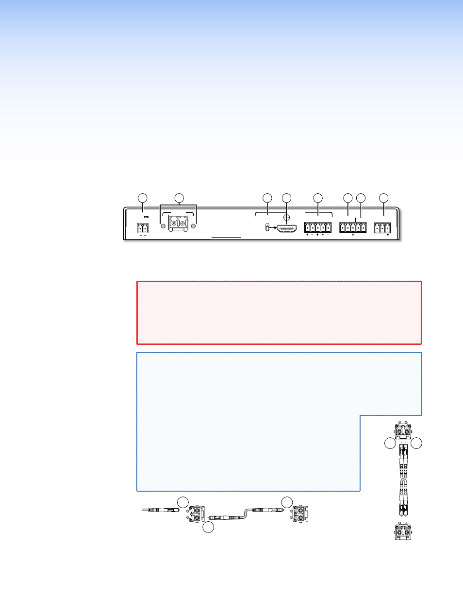
Rear Panel Features
FOXBOX SR HDMI
LINK
LINK
OPTICAL
Rx
Tx
HDMI
AUDIO
OUTPUTS
REMOTE
RS-232
Tx Rx
RS-232
OVER FIBER ALARM
Tx Rx
1 2
POWER
12V
1.0 A MAX
L
R
OFF
ON
HDMI AUDIO
1
4
3
2
8
5
7
6
Figure 2.
FOXBOX SR HDMI Scaling Receiver Rear Panel Features
a
Fiber optic connectors and LEDs —
WARNING: Risk of eye injury: The FOXBOX SR HDMI outputs continuous
invisible light, which may be harmful to the eyes; use with caution.
•
Do not look into the rear panel fiber optic cable connectors or into
the fiber optic cables themselves while the receiver is powered on.
•
Plug the attached dust caps into the optical transceivers when the
fiber cable is unplugged.
NOTE: You can connect the transmitter to one or more receivers in one of three
ways:
•
One-way (transmitter Tx to receiver Rx) only — Connect fiber cable
Ä
from the transmitter Tx connector only.
•
Two-way (transmitter to receiver and return) — Connect fiber
cable
Ä
from the transmitter Tx connector and fiber cable
Å
back to
the transmitter Rx connector (see figure 3).
•
One-way (transmitter to receiver) with daisy
chain (receiver to receiver) — Connect fiber
cable
Ä
from a fiber optic source and cable
Å
to
the next receiver in the daisy chain (see figure 4).
Set each receiver in the daisy chain to daisy chain
mode. Up to 10 properly-configured receivers can be
connected in a daisy chain to a single transmitter.
From Transmitter
or Daisy-Chained
Receiver
Receiver
Receiver
1b
1a
1a
Tx
Rx
Tx
Rx
Figure 4.
Daisy Chain Configuration
Figure 3.
Two Way
Configuration
Transmitter
Receiver
1b
1a
Tx
Rx
Tx
Rx
FOXBOX SR HDMI • Installation
4