Quick start — dds 402, Installation, Step 1 – Extron Electronics DDS 402 User Manual
Page 3: Step 2, Step 3, Step 4, Step 5, Step 6, Qs-1, Rear panel video outputs
QS-1
Quick Start — DDS 402
Installation
Step 1
Turn off power to the DDS 402 and input and out-
put devices, and remove power cords from them.
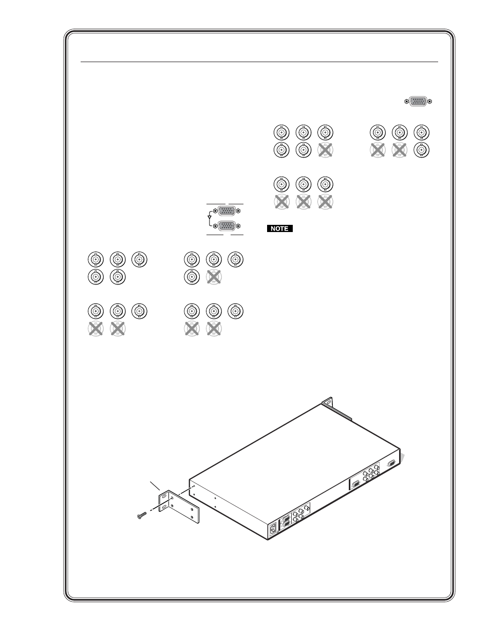
Step 2
Install four rubber feet on the bottom of the
DDS 402, or mount the DDS to furniture or in a rack
(see figure on the bottom of this page).
Step 3
Attach input devices to the DDS.
Input 1:
RGB with buffered local
monitor
Input 2:
RGB or component
video
R
/R-Y
G
/Y
B
/B-Y
R
/R-Y
G
/Y
B
/B-Y
H
/HV
V
H
/HV
V
R
/R-Y
G
/Y
B
/B-Y
H
/HV
V
RGBHV video
RGBS video
RGsB video
Component video (R-Y, B-Y, Y)
R
/R-Y
G
/Y
B
/B-Y
H
/HV
V
Step 4
Attach output devices to the DDS 402.
Rear panel video outputs
RGB or HDTV component video
output
(15HD)
RGB or HDTV component video output
(6 BNCs)
V
H
RGBHV video
RGBS video
Component video (R-Y, B-Y, Y)
S
S
H
V
R
/R-Y
G
/Y
B
/B-Y
R
/R-Y
G
/Y
B
/B-Y
V
H
S
R
/R-Y
G
/Y
B
/B-Y
The two video output connectors, the 15HD
connector and the five BNC connectors, both
output the same video signal and the same
sync format.
Step 5
Plug the DDS 402 and input and output devices
into a grounded AC source, and turn on the input
and output devices. The figure on the following
page shows a typical application.
Step 6
Use the LCD menu screens (see the next page) or
RS-232 programming to configure the DDS 402.
See chapter 2 for installation, chapter 3 for front
panel operation, and chapters 4 and 5 for
RS-232 operation.
RGB
1
RGB/R-Y, B-Y, Y
2A MAX
100-240V 50-60Hz
REMO
TE
RGB/HD R-Y
, B-Y
, Y
RGB/R-Y
, B-Y
, Y
RGB
RGB/R-Y
, B-Y
, Y
2
1
R
/R
Y
G
/Y
B
/B-Y
H
V
S
R
/R
Y
G
/Y
B
/B-Y
H
V
S
O
U
T
P
U
T
S
I
N
P
U
T
S
Rack-mount
Bracket