Diameter bolts to 40 ft. lbs. and – Bell & Gossett HT 205B SM Models ACA Straight Tube, Removable Bundle Heat Exchangers User Manual
Page 5
CAUTION: Model MEAH (which has the long steel hor-
izontal baffle (N) with the rubber baffle sealing strips (O)
adhered to the horizontal baffle):
The rubber baffle strips (O) are sealing strips between the shell (C)
and horizontal baffle (N). The rubber baffle strips (O) must curl
along the shell (C) towards the shell’s liquid inlet connection. The
liquid pressure forces the rubber baffle strips against shell and
seals it. This is shown in Illustration No. 7.
NOTE: When replacing heads use a torque wrench.
a. On heads (front heads) with gaskets, tighten
1
/
2
" diameter bolts
to 40 ft. lbs. and
5
/
8
" diameter bolts to 80 ft. lbs. If the gasket
joint still leaks, tighten in 5 ft. lbs. increments until leak stops.
b. On heads with packing (rear heads), tighten initially to 50 ft.
lbs. If the packing still leaks tighten in 5 ft. lbs. increments until
leak stops. Do not exceed 100 ft. lbs. on the bolts for the
packed heads.
*The above torque values apply to well lubricated nut bearing
surfaces.
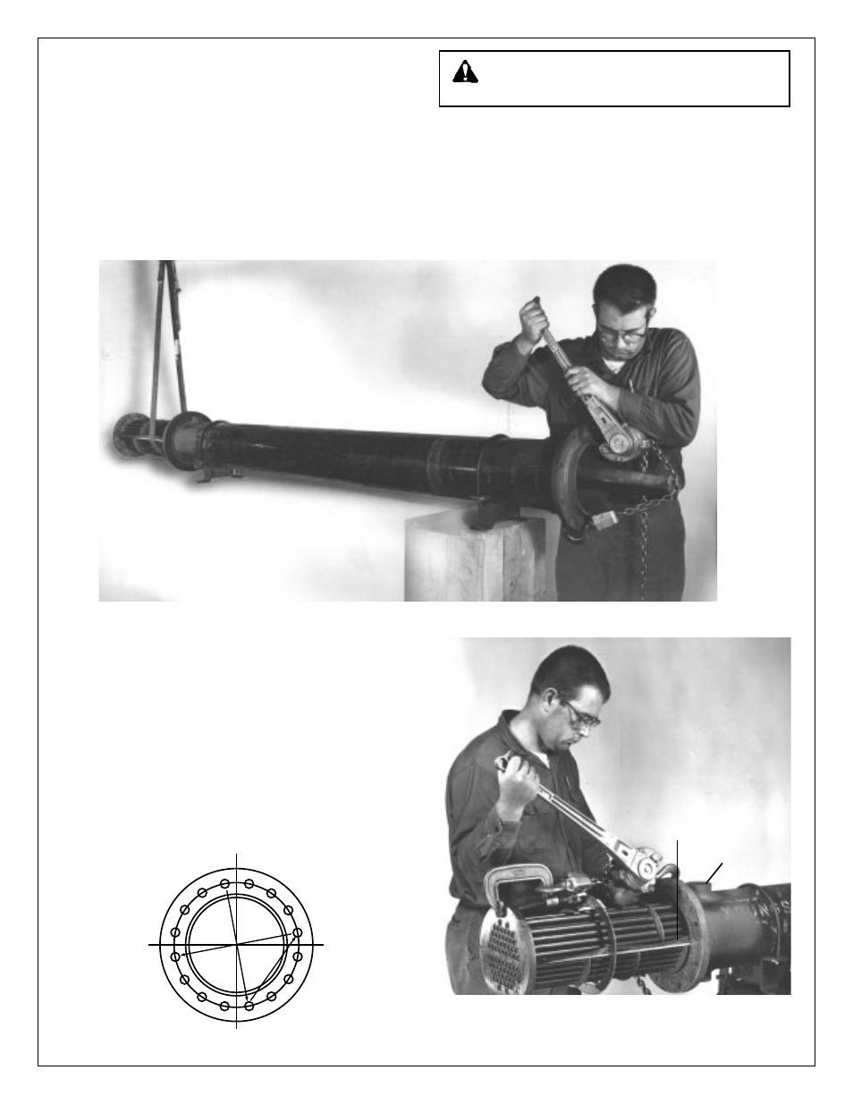
All bolted joints should be tightened uniformly and in a diametri-
cally staggered pattern as illustrated below:
10. Replacing the tube bundle:
The tube bundles for models ACA, GC, MEA, MEAH and OC
(the packed floating tube sheet units) can be replaced using
the tools and reverse procedure given for bundle removal.
Usually, the bundles ACA, GC, MEA and OC, can be shoved
back into the shell (C) manually without the use of the chain
jack.
It may be necessary to use the chain jack when replacing
MEAH bundles.
1
2
3
4
6
9
14
7
15
12
5
10
13
8
11
16
START
Illustration No. 6 – Removal of tube bundle showing method of tube bundle support.
Illustration No. 7 – Position of rubber baffle strips and liquid inlet in
relation to each other when assembling unit.
5
BUNA STRIP
(Must curl upward
as shown)
LIQUID INLET