Bell & Gossett A07258B Check-Trol Flange User Manual
Check-trol, Flange, Instruction manual
INSTALLER: PLEASE LEAVE THIS MANUAL FOR THE OWNER’S USE.
Check-Trol
™
Flange
SAFETY
INSTRUCTION
This safety alert symbol will be used in this manual to draw attention to
safety related instructions. When used, the safety alert symbol means
ATTENTION! BECOME ALERT! YOUR SAFETY IS INVOLVED! FAIL-
URE TO FOLLOW THESE INSTRUCTIONS MAY RESULT IN A
SAFETY HAZARD.
DESCRIPTION
The Check-Trol™ Flange is a combination of an isolation valve, a spring
check valve and a companion flange for circulators. The Check-Trol™
flange allows easy service or replacement of the circulator without the
need to drain the system. The spring check valve prevents system fluid
from flowing in the wrong direction or unwanted direction. The spring
check valve also prevents gravity flow.
INSTALLATION INSTRUCTIONS
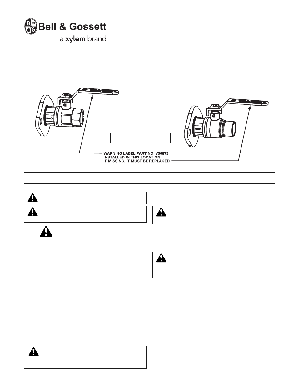
1. Install the Check-Trol™ Flange on the discharge side of the pump
with arrow pointing in the direction of flow (the Check-Trol™ Flange
has “Check-Trol™” written on handle). Install the Isolation Flange
(without Check Valve) on the suction side of the pump.
2. See the following installation instructions and drawings for additional
information.
3. Apply torque in even increments to both flange bolts. Refer to the
pump manufacturers instruction manual for torque value. Both the
suction and discharge flanges must be torqued in this manner.
For Check-Trol™ & Isolation Flange NPT Connections:
a) Apply pipe compound conservatively to the male connecting fittings
only.
b) Upon completion of valves installation to piping, check connections
for leaks.
For Check-Trol™ & Isolation Flange Sweat Connections:
a) For soldering, use 95-5 (Tin-Antimony) solder and a good grade of
flux. Solder end valves are suitable for soldering without disassem-
bly. Refer to table 1 for solder types and temperatures. Solder joint
strength and working pressure varies with tube size, solder grade
and temperature as defined in ASME B16.18 and B16.22. Do not
exceed the limits stated in table 1.
b) Cut the tube square and deburr both ID and OD. Do not deform the
tube, otherwise it must be re-sized. Clean tube end and valve solder
cup with abrasive cloth or wire brush until the surfaces are bright
metal. Alternatively use an approved cleaning paste: in this case
spread the paste evenly on the tube; insert the tube into the cup and
turn to distribute the paste; finally remove the excess paste.
c) When sweating joints, first wrap the valve body with a cool wet rag,
then direct the flame with care to avoid subjecting the valve to ex-
cessive heat. Allow the valve to cool before touching or operating.
The valve must be in the fully closed position during soldering. Valve
seats may be damaged if soldering is done in the open or partly open
position.
Max Temperature 200°F (93°C)
Max Pressure 150psig (10 Bar)
Operational Limits
NPT
CONNECTION
SWEAT
CONNECTION
WARNING: System fluids under temperature or pressure
can be hazardous. Be sure the pressure is relieved and
system temperature is below 100°F (38°C). Failure to follow these in-
structions could result in property damage and/or personal injury.
WARNING: To prevent leakage, make certain that the flange
bolts have been adequately torqued. Failure to follow these
instructions could result in personal injury and/or property damage.
CAUTION: Over-tightening and breakage can occur with the
use of teflon pipe joint compounds. Teflon provides lubricity
so that care must be exercised not to over-tighten joints. Failure
to follow these instructions could result in property damage and/or
personal injury.
WARNING: Wetted surface contains not more than 0.25%
of lead by weight.
WARNING: California Proposition 65 Warning! This product
contains chemicals known to the State of California to cause
cancer and birth defects or other reproductive harm.
INSTRUCTION MANUAL
A07258B