New prod uc t al8807b, Applications information, On off – Diodes AL8807B User Manual
Page 13
AL88070B
Document number: DS36191 Rev. 1 - 2
13 of 18
March 2014
© Diodes Incorporated
NEW PROD
UC
T
AL8807B
Applications Information
(cont.)
Inductor Selection
(cont.)
The chosen coil should have a saturation current higher than the peak output current and a continuous current rating above the required mean
output current.
Suitable coils for use with the AL8807B are listed in the table below:
Part No.
L
(µH)
DCR
(V)
I
SAT
(A)
Manufacturer
MSS1038-333 33
0.093 2.3
MSS1038-683 68
0.213 1.5
NPIS64D330MTRF 33 0.124 1.1
The inductor value should be chosen to maintain operating duty cycle and switch 'on'/'off' times over the supply voltage and load current range.
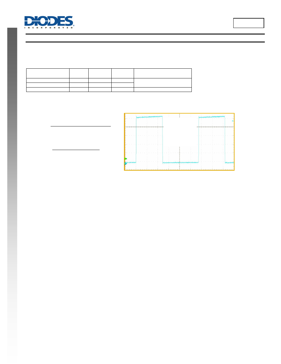
The following equations can be used as a guide, with reference to Figure 38 – typical switching waveforms.
Switch ‘On’ time
R
r
R
x
I
V
V
I
L
t
SW
L
S
AVG
LED
IN
ON
Switch ‘Off’ time
r
R
x
I
V
V
I
L
t
L
S
AVG
D
LED
OFF
Where:
L is the coil inductance (H)
r
L
is the coil resistance (Ω)
R
S
is the current sense resistance (Ω)
I
avg
is the required LED current (A)
∆I is the coil peak-peak ripple current (A)
{Internally set to 0.3 x Iavg}
V
IN
is the supply voltage (V)
Figure 38 Typical Switching Waveform
V
LED
is the total LED forward voltage (V)
R
SW
is the switch resistance (Ω) {=0.5Ω nominal}
V
D
is the diode forward voltage at the required load current (V)
Thermal Protection
The AL8807B includes Over-Temperature Protection (OTP) circuitry that will turn off the device if its junction temperature gets too high. This is to
protect the device from excessive heat damage. The OTP circuitry includes thermal hysteresis that will cause the device to restart normal
operation once its junction temperature has cooled down by approximately 55°C.
Thermal Considerations
For continuous conduction mode of operation, the absolute maximum junction temperature must not be exceeded. The maximum power
dissipation depends on several factors: the thermal resistance of the IC package
JA
, PCB layout, airflow surrounding the IC, and difference
between junction and ambient temperature.
The maximum power dissipation can be calculated using the following formula:
P
D(MAX)
= (T
J(MAX)
− T
A
) /
JA
where
T
J(MAX)
is the maximum operating junction temperature Maximum recommended = 125°C
T
A
is the ambient temperature, and
JA
is the junction to ambient thermal resistance.
JA
, is layout dependent and package dependent; the AL8807BMP’s
JA
on an FR4 51x51mm PCB with 2oz copper standing in still air is
approximately 69°C/W.
So the maximum power dissipation at T
A
= +25°C is:
P
D(MAX)
= (125°C − 25°C) / (69°C/W) = 1.41W for the above dimensioned PCB
V
IN
= 12V
T
A
=25ºC
2 LEDs
20ns/div
SW Pin: 2V/div
On
Off