New prod uc t al8807b, Applications information – Diodes AL8807B User Manual
Page 10
AL88070B
Document number: DS36191 Rev. 1 - 2
10 of 18
March 2014
© Diodes Incorporated
NEW PROD
UC
T
AL8807B
Applications Information
(cont.)
PWM Dimming
LED current can be adjusted digitally, by applying a low frequency Pulse Width Modulated (PWM) logic signal to the CTRL pin to turn the device
on and off.
This will produce an average output current proportional to the duty cycle of the control signal. In particular, a PWM signal with a max resolution of
10bit can be applied to the CTRL pin to change the output current to a value below the nominal average value set by resistor R
SET
.
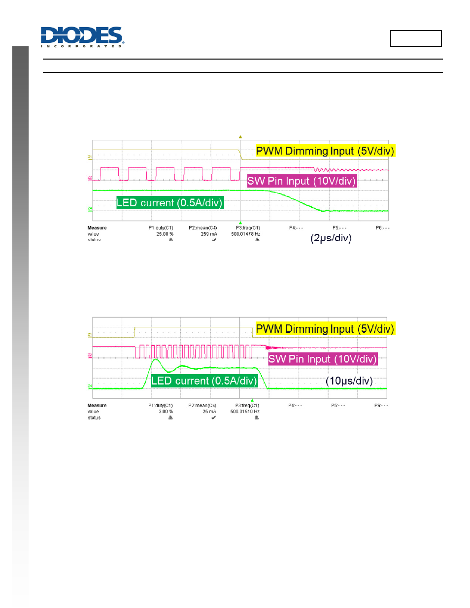
Figure 33 PWM Dimming waveforms (f
PWM
= 500Hz, 25% Duty Cycle f
SW(NOM)
= 530kHz)
While the PWM pin is high, the AL8807B switches as normal. When the PWM pin is brought low the output switch is turned off causing the SW pin
to go high (one Schottky voltage drop above V
IN
). It remains high (one Schottky voltage drop above V
IN
) until the current through the inductor falls
to zero. The time taken for the inductor current is dependent on the LED current, inductor value and LED chain voltage.
As the duty cycle gets smaller or PWM dimming frequency increases then fewer normal hysteretic switching cycles occur which will affect the
overall average LED current.
Figure 34 PWM Dimming waveforms (f
PWM
= 500Hz, 2% Duty Cycle f
SW(NOM)
= 530kHz)
To achieve high resolution the PWM frequency has to be much lower than the nominal switching frequency and the LED current output filter
capacitor across the LEDs must not be used. The figures above have an LED current output filter present.