Applications information, Fd t – Diodes AL9910/ AL9910A/ AL9910-5/ AL9910A-5 User Manual
Page 9
AL9910/ AL9910A/ AL9910-5/ AL9910-5A
Document number: DS35103 Rev. 9 - 2
9 of 15
May 2014
© Diodes Incorporated
AL9910/ AL9910A/ AL9910-5/ AL9910A-5
Applications Information
(cont.)
Dimming
The LED brightness can be dimmed either linearly (using the LD pin) or via pulse width modulation (using the PWM-D pin); or a combination of
both - depending on the application. Pulling the PWM_D pin to ground will turn off the AL9910. When disabled, the AL9910’s quiescent current is
typically 0.5mA (0.65 for AL9910A). Reducing the LD voltage will reduce the LED current but it will not entirely turn off the external power
transistor and hence the LED current – this is due to the finite blanking period. Only the PWM_D pin will turn off the power transistor.
Linear dimming is accomplished by applying a 45mV to 250mV analog signal to the LD pin. This overrides the default 250mV threshold level of the
CS pin and reduces the output current. If an input voltage greater than 250mV is applied to the LD then the output current will not change.
The LD pin also provides a simple cost effective solution to soft start; by connecting a capacitor to the LD pin down to ground at initial power up
the LD pin will be held low causing the sense threshold to be low. As the capacitor charges up the current sense threshold will increase thereby
causing the average LED current to increase.
PWM dimming is achieved by applying an external PWM signal to the PWM_D pin. The LED current is proportional to the PWM duty cycle and the
light output can be adjusted between zero and 100%. The PWM signal enables and disables the AL9910 - modulating the LED current. The
ultimate accuracy of the PWM dimming method is limited only by the minimum gate pulse width, which is a fraction of a percentage of the low
frequency duty cycle. PWM dimming of the LED light can be achieved by turning on and off the converter with low frequency 50Hz to 1000Hz TTL
logic level signal.
With both modes of dimming it is not possible to achieve average brightness levels higher than the one set by the current sense threshold level of
the AL9910. I
f a greater LED current is required then a smaller
sense resistor should be used
Output Open Circuit Protection
The non-isolated buck LED driver topology provides inherent protection against an open circuit condition in the LED string due to the LEDs being
connected in series with the inductor. Should the LED string become open circuit then no switching occurs and the circuit can be permanently left
in this state with damage to the rest of the circuit.
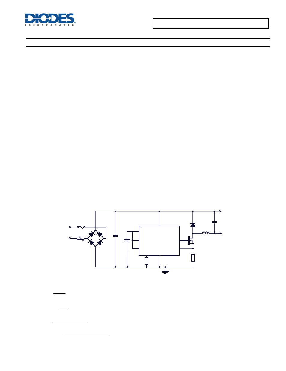
AC/DC Off-Line LED Driver
The AL9910 is a cost-effective off-line buck LED driver-controller specifically designed for driving LED strings. It is suitable for being used with
either rectified AC line or any DC voltage between 15V to 500V. See Figure 3 for typical circuit.
Figure 3. Typical Application Circuit (without PFC)
Buck Design Equations:
=
D
IN
LEDs
V
V
osc
ON
f
D
t
=
≥
L
LED
ON
LEDs
IN
I
3
.
0
t
)
V
V
(
Ч
Ч
−
=
SENSE
R
))
3
.
0
I
(
5
.
0
(
I
25
.
0
LED
LED
Ч
Ч
+
where I
LED
x 0.3 = I
RIPPLE
R
SENSE
AL9910/A
GATE
CS
LD
PWM_D
GND
R
OSC
V
DD
V
IN
LED +
LED -
V
AC
IN
Q1
L1
D1
C1
R
OSC
C2
C3
BR1
R
SENSE
AL9910/A
GATE
CS
LD
PWM_D
GND
R
OSC
V
DD
V
IN
LED +
LED -
V
AC
IN
Q1
L1
D1
C1
R
OSC
C2
C3
BR1