Al9910/a, Applications information – Diodes AL9910/ AL9910A/ AL9910-5/ AL9910A-5 User Manual
Page 11
AL9910/ AL9910A/ AL9910-5/ AL9910-5A
Document number: DS35103 Rev. 9 - 2
11 of 15
May 2014
© Diodes Incorporated
AL9910/ AL9910A/ AL9910-5/ AL9910A-5
Applications Information
(cont.)
DC-DC Buck LED Driver
The design procedure for an ac input buck LED driver outlined in the previous chapters equally applies DC input LED drivers.
When driving long LED chains care should be taken not to induce SBO – maximum LED chain voltage should be less half of V
IN
. So either
maximum duty cycle should be kept below 50% or use of constant off-time removes this issue.
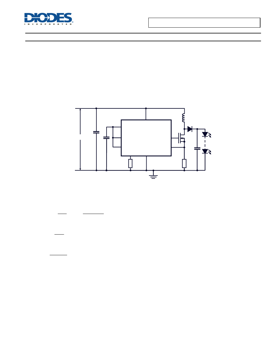
DC-DC Boost LED Driver
Due to the topology of the AL9910 LED driver-controller it is capable of being used in boost configurations – at reduced accuracy. The accuracy
can be improved by measuring the LED current with an op amp and use the op amp’s output to drive the LD pin.
A Boost LED driver is used when the forward voltage drop of the LED string is higher than the input supply voltage. For example, the Boost
topology can be appropriate when input voltage is supplied by a 48V power supply and the LED string consists of twenty HB LEDs, as the case
may be for a street light.
Figure 5. Boost LED Driver
In a Boost converter, when the external MOSFET is ON the energy is stored in the inductor which is then delivered to the output when the external
MOSFET switches OFF. If the energy stored in the inductor is not fully depleted by the next switching cycle (continuous conduction mode) the
DC conversion between input and output voltage is given by:
D
1
V
V
IN
OUT
−
=
Î
OUT
IN
OUT
V
V
V
D
−
=
From the switching frequency, f
OSC
, the on-time of the MOSFET can be calculated:
OSC
ON
f
D
t
=
From this the required inductor value can be determined by:
LED
ON
IN
I
3
.
0
t
V
L
∗
∗
=
The Boost topology LED driver requires an output capacitor to deliver current to the LED string during the time that the external MOSFET is on.
In boost LED driver topologies if the LEDs should become open circuit damage may occur to the power switch and so some form of detection
should be present to provide Over-voltage detection/protection.
R
SENSE
AL9910/A
GATE
CS
LD
PWM_D
GND
R
OSC
V
DD
V
IN
Q1
L1
D1
C1
R
OSC
C2
C3
V
IN