Application information, Design parameters – Diodes AL9910/ AL9910A/ AL9910-5/ AL9910A-5 User Manual
Page 7
AL9910/ AL9910A/ AL9910-5/ AL9910-5A
Document number: DS35103 Rev. 9 - 2
7 of 15
May 2014
© Diodes Incorporated
AL9910/ AL9910A/ AL9910-5/ AL9910A-5
Application Information
The AL9910 is very versatile and is capable of operating in isolated or non-isolated topologies. It can also be made to operate in continuous as
well as discontinuous conduction mode.
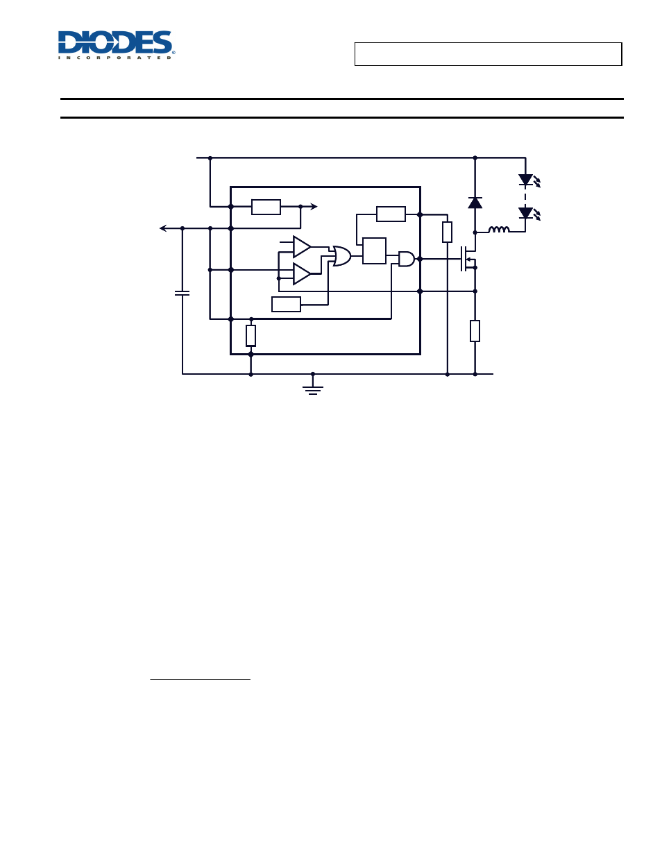
Figure 1 Functional Block Diagram
The AL9910 contains a high voltage LDO (see Figure 1) the output of the LDO provides a power rail to the internal circuitry including the gate
driver. A UVLO on the output of the LDO prevents incorrect operation at low input voltage to the V
IN
pin.
In a non-isolated Buck LED driver when the gate pin goes high the external power MOSFET Q1 is turned on causing current to flow through the
LEDs, inductor (L1) and current sense resistor (R
SENSE
). When the voltage across R
SENSE
exceeds the current sense pin threshold the external
MOSFET Q1 is turned off. The stored energy in the inductor causes the current to continue to flow through the LEDs via diode D1.
The AL9910’s LDO provides all power to the rest of the IC including Gate drive this removes the need for large high power start-up resistors. This
means that operate correctly it requires around 0.5mA from the high voltage power rail. The LDO can also be used to supply up to 1mA to external
circuits.
The AL9910 operates and regulates by limiting the peak current of the external MOSFET; the peak current sense threshold is nominally set at
250mV.
The same basic operation is true for isolated topologies, however in these the energy stored in the transformer delivers energy to LEDs during the
off-cycle of the external MOSFET.
Design Parameters
Setting the LED Current
In the non-isolated buck converter topology, figure 1, the average LED current is not the peak current divided by 2 - however, there is a certain
error due to the difference between the peak and the average current in the inductor. The following equation accounts for this error:
(
)
))
I
*
5
.
0
(
I
mV
250
R
RIPPLE
LED
SENSE
+
=
.
250mV
LD
V
DD
LDO
V
IN
OTP
PWM_D
GND
7.5/10V
OSC
S
R
O
R
OSC
GATE
CS
100k
V
DD
V
IN
R
SENSE
AL9910/AL9910A
250mV
LD
V
DD
LDO
V
IN
OTP
PWM_D
GND
7.5/10V
OSC
S
R
O
R
OSC
GATE
CS
100k
V
DD
V
IN
R
SENSE
AL9910/AL9910A