Applications information, Al9910/a – Diodes AL9910/ AL9910A/ AL9910-5/ AL9910A-5 User Manual
Page 10
AL9910/ AL9910A/ AL9910-5/ AL9910-5A
Document number: DS35103 Rev. 9 - 2
10 of 15
May 2014
© Diodes Incorporated
AL9910/ AL9910A/ AL9910-5/ AL9910A-5
Applications Information
(cont.)
Design Example
For an AC line voltage of 120V the nominal rectified input voltage V
IN
= 120V*1.41 = 169V. From this and the LED chain voltage the duty cycle
can be determined:
D = V
LEDs
/V
IN
= 30/169 = 0.177
From the switching frequency, for example f
OSC
= 50kHz, the required on-time of the external MOSFET can be calculated:
t
ON
= D/f
OSC
= 3.5 µs
The value of the inductor for an LED current of 350mA is determined as follows:
L = (V
IN
- V
LEDs
) * t
ON
/(0.3 * I
LED
) = 4.6mH
Input Bulk Capacitor
For Offline lamps an input bulk capacitor is required to ensure that the rectified AC voltage is held above twice the LED string voltage throughout
the AC line cycle. The value can be calculated from:
≥
IN
C
MAX
_
DC
L
MIN
_
LINE
CH
IN
V
f
2
V
2
)
D
1
(
P
Δ
Ч
Ч
Ч
−
Ч
Where
ch
D
: Capacity charge work period, generally about
0.2 to 0.25
L
f
: Input frequency for full range
(85 to 265V
RMS
)
MAX
_
DC
V
Δ
Should be set
10 to15% of
MIN
_
LINE
V
2
If the capacitor has a 15% voltage ripple then a simplified formula for the minimum value of the bulk input capacitor approximates to:
C
MIN
=
2
IN
LEDs
LED
V
0.06
V
I
Ч
Ч
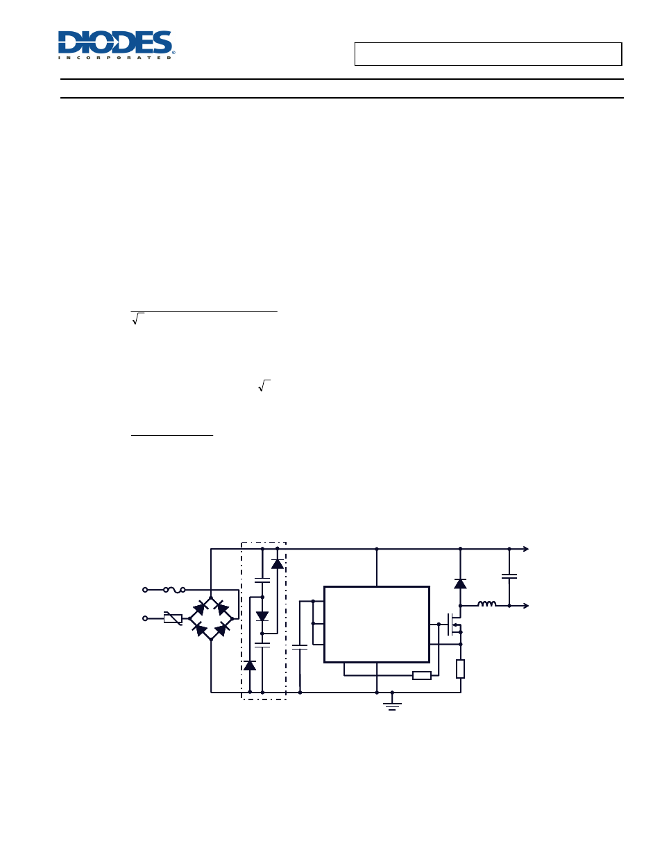
Power Factor Correction
If power factor improvement is required then for the input power less than 25W, a simple passive power factor correction circuit can be added to
the AL9910 typical application circuit. Figure 4 shows that passive PFC circuitry (3 current steering diodes and 2 identical capacitors) does not
significantly affect the rest of the circuit. Simple passive PFC improves the line current harmonic distortion and achieves a power factor greater
than 0.85.
Figure 4. Typical Application Circuit with Passive PFC
Each of these identical capacitors should be rated for half of the input voltage and have twice as much capacitance as the calculated C
MIN
of the
buck converter circuit without passive PFC (see above section on bulk capacitor calculation).
For further design information please see AN75 from the Diodes website.
R
SENSE
AL9910/A
GATE
CS
LD
PWM_D
GND
R
OSC
V
DD
V
IN
LED +
LED -
V
AC
IN
Q1
L1
D1
R
OSC
C3
C4
BR1
Passive PFC
C1
C2
R
SENSE
AL9910/A
GATE
CS
LD
PWM_D
GND
R
OSC
V
DD
V
IN
LED +
LED -
V
AC
IN
Q1
L1
D1
R
OSC
C3
C4
BR1
Passive PFC
C1
C2