Data sheet, Electrical characteristics (continued), Parameter symbol test condition min typ max unit – Diodes AUR9807 User Manual
Page 9
Data Sheet
Single-cell Li-Ion Charger IC with System Power Management AUR9807
Nov. 2011 Rev. 1. 0 BCD Semiconductor Manufacturing Limited
9
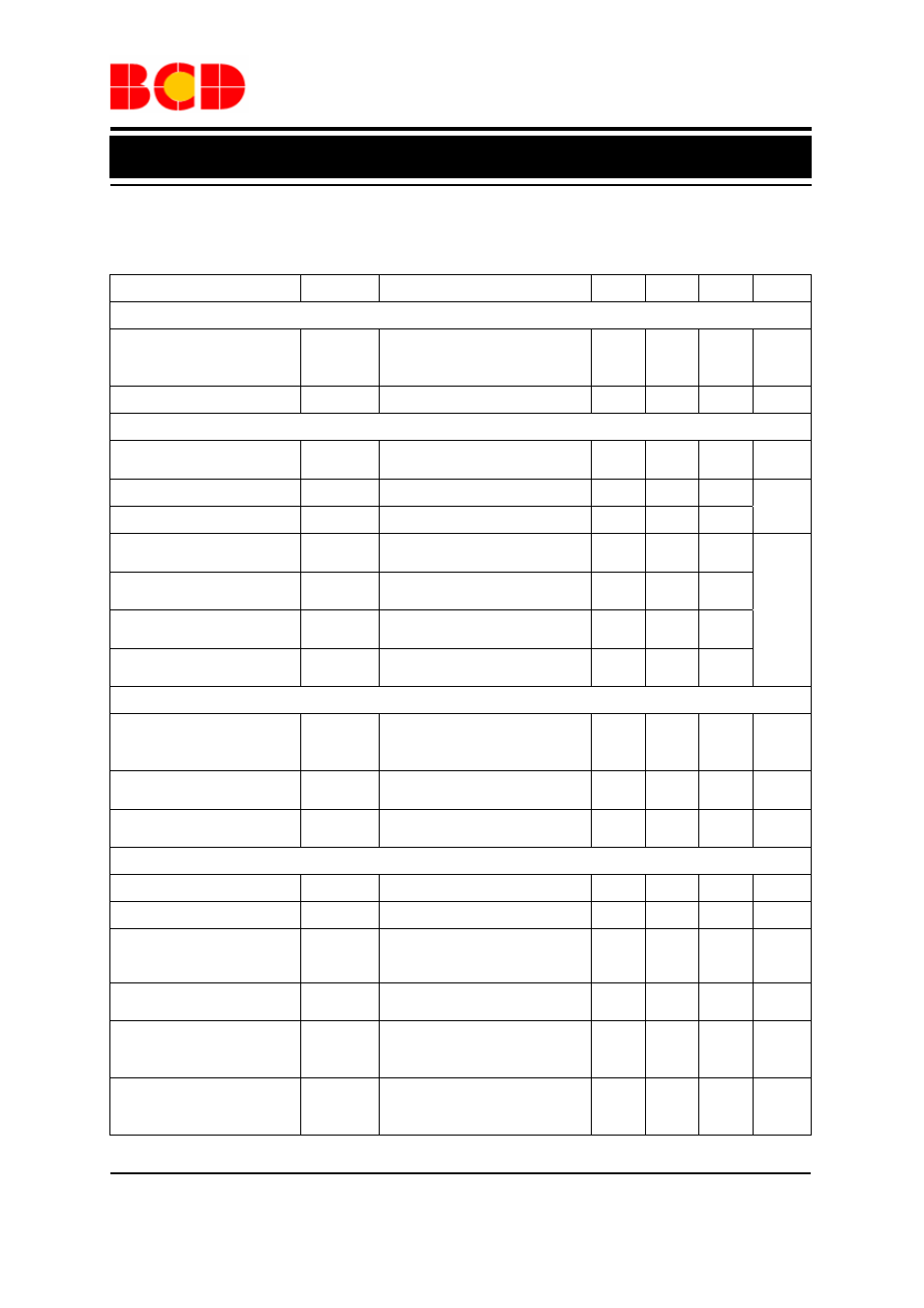
Electrical Characteristics (Continued)
T
A
=25
o
C, V
IN
is within the recommended range, unless otherwise specified.
Parameter Symbol
Test
Condition
Min
Typ
Max
Unit
STAT1, STAT2, AND
/PG
Low-level Output
Saturation Voltage
V
OL
I
OL
=5mA, requiring an
external pull-up resistor>
1kΩ
0.25
V
Input Leakage Current
I
LKG
1
5
µA
ISET2, CE
CE Pin Hold-off Time
t
CE-HLDOF
F
CE fall low only
4
6
ms
Low-level Input Voltage
V
IL
0
1.1
High-level Input Voltage
V
IH
1.5
V
CE Pin
Low-level Input Current
I
IL1
-1
CE Pin
High-level Input Current
I
IH1
1
ISET2 Pin
Low-level Input Current
I
IL2
V
ISET2
=0.4V -20
ISET2 Pin
High-level Input Current
I
IH2
V
ISET2
=V
IN
40
µA
MODE
Mode Pin
Low-level Input Voltage
V
IL
Falling Hi→Low;
280kΩ±10% applied when
low
0.975
1 1.025 V
Mode Pin
High-level Input Voltage
V
IH
Input R
MODE
sets external
hysteresis
V
IL
+
0.01
V
IL
+
0.024
V
Mode Pin
Low-level Input Current
I
IL
-1
µA
TIMERS
Timer Set Factor
K
TMR
t
CHG
=K
TMR
x R
TMR
0.313
0.36
0.414
s/Ω
External Resistor Limits
R
TMR
30
100
kΩ
Precharge Timer
t
PRECHG
0.115
x
t
CHG
0.125
x
t
CHG
0.135
x
t
CHG
s
Timer Fault Recovery
Pull-up from OUT to BAT
R
FAULT
1
kΩ
Time Out Extension
Factor1
K
EXT1
The actual charge current less
than 50% of maximum fast
charge current
2
Time Out Extension
Factor2
K
EXT2
The actual charge current less
than 25% of maximum fast
charge current
4