Data sheet, Pin description – Diodes AUR9807 User Manual
Page 3
Data Sheet
Single-cell Li-Ion Charger IC with System Power Management AUR9807
Nov. 2011 Rev. 1. 0 BCD Semiconductor Manufacturing Limited
3
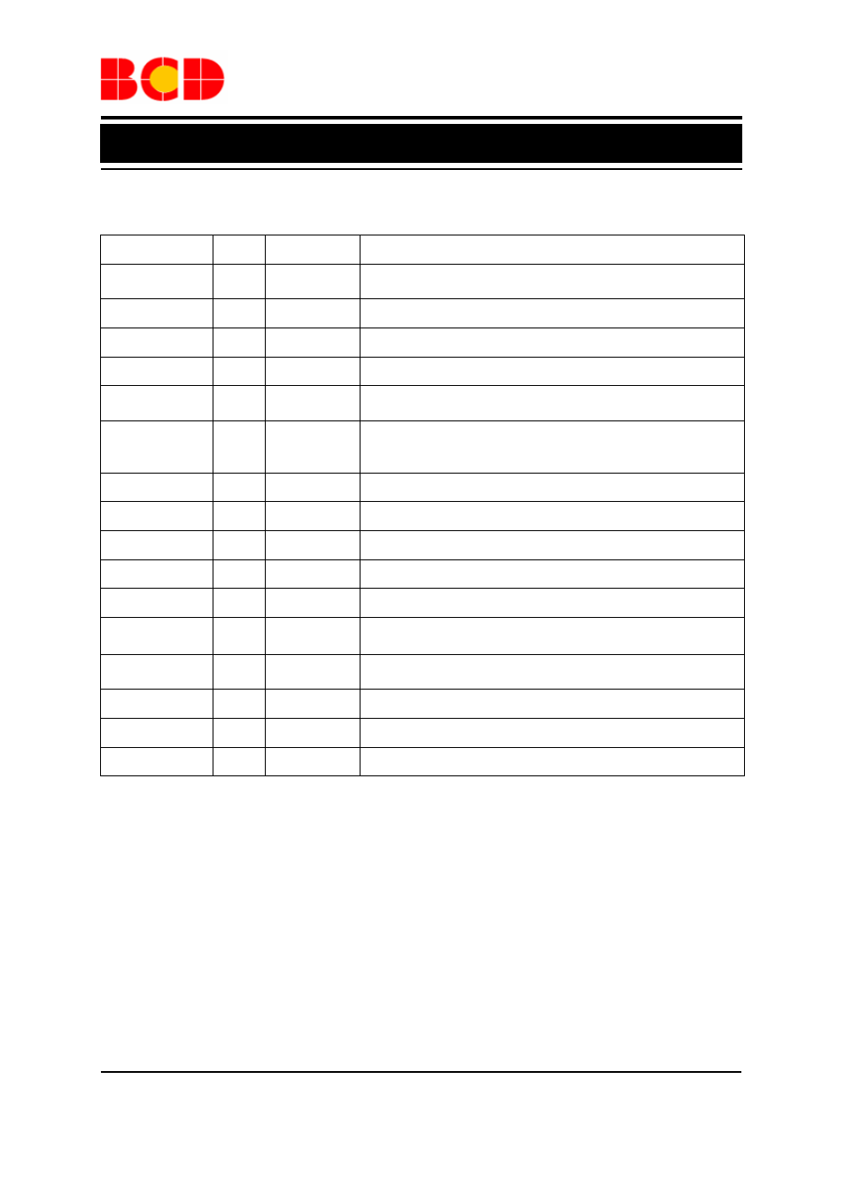
Pin Description
Pin Number
I/O
Pin Name
Function
1 O
VREF
Internal reference; VREF output capacitor not required, but
one with a value of 0.1µF is recommended.
2
O
STAT1
Charge status flag 1 (open-drain)
3
O
STAT2
Charge status flag 2 (open-drain)
4 I
IN
Chip
input
voltage
5 , 6
I/O
BAT
Battery connection; charging or discharging all through this
pin
7 I
ISET2
USB mode total current selection (High=450mA, Low=
90mA) and AC mode charge current selection (High=Full
current, Low=half current)
8
I
MODE
Set AUR9807 in AC(High) or USB(Low) mode
9
I
CE
Chip enable (active high)
10
I/O
ISET1
Set the maximum charging current
11
I
SYSOFF
Cut off the power path between the battery and the output pin
12 I/O
TS
Battery
Temperature
sensing
13 I
APM
Active Power Management set point ※ no need for
capacitors
14 I/O
TMR
Timer program by external resistor connected to this pin.
Tying TMR and VREF together to disable the safety timer
15 , 16 , 17
O
OUT
System output
18
O
/PG
Power-good status flag (open-drain)
19 , 20
I
GND
Chip Ground