Data sheet, Charge function descriptions (continued) – Diodes AUR9807 User Manual
Page 16
Data Sheet
Single-cell Li-Ion Charger IC with System Power Management AUR9807
Nov. 2011 Rev. 1. 0 BCD Semiconductor Manufacturing Limited
16
Charge Function Descriptions (Continued)
The maximum charging current, the pre-charge
current and charge done current setting are given in
the above table. The charging process begins with a
pre-charge phase; when the battery voltage reaches
the pre-charge threshold V
LOWV
, the charger enters
the constant current mode. At this stage, the charger
tries to charge the battery with the maximum
charging current (a constant); however, the actual
charging current may be lower due to Active Power
Management activated by large system loading or
insufficient input current capability. The thermal
fold-back mechanism also reduces the actual
charging current when the junction temperature is
over 110°C. The battery voltage rises gradually with
the constant current entering the battery.
When the battery voltage reaches V
BAT(REG)
, the
charger enters the constant voltage mode. At this
stage, the charger keeps the battery voltage at
V
BAT(REG)
with a decreasing charging current. When
the charging current drops below the charge done
current setting, nominally the charging process is
complete (this can be observed from the external
indicator). Depending on different versions, after the
charge done status indicated, the charger will stop
providing charging current completely or stay in
constant voltage mode till time out. When the battery
voltage drops below the recharge threshold, a new
charge cycle begins.
Example:
With a R
SET
=1kΩ, the maximum charging current is
about 1A for ISET2=High and 0.5A for ISET2=Low.
The pre-charge current I
PRECHG
is 100mA. The charge
done current setting is 100mA for AC mode and
40mA for USB mode. Note the absolute values of
pre-charge current and charge done current setting do
not vary with ISET2.
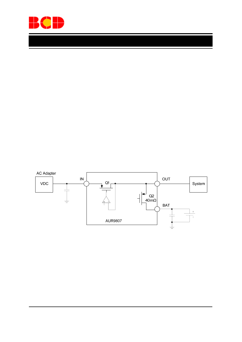
Power Source Selecting
OUT
RE
F
i.
V
IN
BAT : V OUT =V BAT –V DO(BAT-OUT) ii. V BAT IN OUT(REG) : V OUT =V IN –V DO(IN-OUT) iii. V OUT(REG) +V DO(IN-OUT) IN <6V: V OUT =V OUT(REG) iv. 6V IN : V OUT =V BAT –V DO(BAT-OUT) IN is lower than V BAT , the battery is responsible to power the system. The output voltage V OUT is V BAT – V DO(BAT-OUT) . When the input voltage V IN is higher than V BAT and lower than 6V, the input source is used to supply the system power; the output voltage IN . When V IN is lower than V OUT(REG) , the output voltage V OUT is V IN –V DO(IN-OUT) ; when V IN is high enough, which means that V IN >(V OUT(REG) + V DO(IN-OUT) ), the output voltage is regulated at V OUT(REG) . When the input voltage V IN is higher than 6V, the current path between IN and OUT is cut off to OUT is then V BAT –V DO(BAT-OUT) .
The AUR9807 selects power source automatically
depending on the voltage present at the input. When
V
depends on V
protect the chip; AUR9807 therefore selects the
Battery as the power source; the output voltage V