Data sheet, Charge function descriptions (continued) – Diodes AUR9807 User Manual
Page 17
Data Sheet
Single-cell Li-Ion Charger IC with System Power Management AUR9807
Nov. 2011 Rev. 1. 0 BCD Semiconductor Manufacturing Limited
17
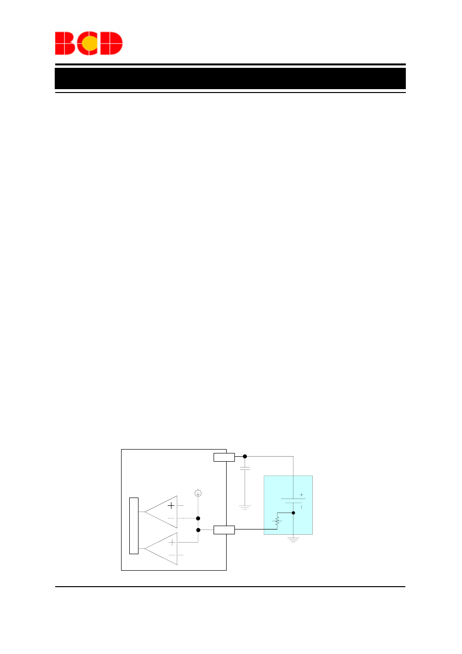
NTC
Li Battery
1µF
BAT
TS
V
LTF
V
HTF
100µA
AUR9807
LO
G
IC UN
IT
Charge Function Descriptions (Continued)
Active Power Management (APM)
AC MODE (MODE=HIGH)
i.
V
APM-REG
OUT : Normal Mode; I CHG determined by R SET ii. V BAT OUT APM-REG : APM mode ; I CHG = I supply max –I OUT iii. V OUT BAT : BAT supply mode USB 500 MODE (MODE=LOW , ISET2=HIGH) i. V APM-REG OUT : Normal Mode; I CHG determined by R SET ii. V BAT OUT APM-REG : APM mode; I CHG = 450mA – I OUT iii. V OUT BAT : BAT supply mode USB 100 MODE (MODE=LOW , ISET2=LOW) i. V APM-REG OUT : Normal Mode; I CHG determined by R SET ii. V BAT OUT APM-REG : APM mode; I CHG = 90mA–I OUT iii. V OUT BAT : BAT supply mode The active power management feature adjusts the APM-REG is given by: APM-REG = I APM-SET ×R APM × SF (4) APM-REG , the input source is capable of providing the charging SET ) and output current (determined by system loading) simultaneously. When the output APM-REG due to an increasing loading, AUR9807 starts to reduce the APM-REG . Because AUR9807 uses the remaining available current to charge the battery, the charging supply max – I OUT . In AC mode, the I supply max is determined by the driving capability of the AC adapter and AUR9807 itself (usually the supply max is about 2A). The I supply max is determined by the ISET2 setting in USB mode (I supply max is about 450mA with ISET2 high, and I supply max is about 90mA with ISET2 low). supply max , the AUR9807 can not prevent the output voltage dropping below V APM-REG even the charging current is reduced to zero. When the output voltage BAT . At this situation, we have: I OUT = I supply max +I BAT (5) (4) R APM <38kΩ: V APM-REG =I APM-SET ×R APM ×SF R APM >41kΩ: The V APM-REG is set to a predetermined fixed value (4.26V) (5) I BAT =(V BAT –V OUT ) / (40mΩ Power Path Resistance) Battery Temperature Protection
charging current to resist the output voltage drop due to
heavy system loading or insufficient input driving
capability. In the extreme situation, the charging current
flow would be reversed (the battery helps to supply the
system power). The active power management
regulation voltage V
V
When the output voltage is higher than V
current (set by R
voltage goes down and reaches V
charging current and tries to keep the output voltage at
V
current can be estimated as I
limiting factor is the AUR9807, and I
When the loading current keeps increasing and exceeds
I
drops below the battery voltage, the battery helps to
supply the loading current and keeps the output voltage
roughly at V