Application information, Zxld1374, A product line of diodes incorporated – Diodes ZXLD1374 User Manual
Page 25
ZXLD1374
Document number: DS35032 Rev. 3 - 2
25 of 39
September 2012
© Diodes Incorporated
ZXLD1374
A Product Line of
Diodes Incorporated
Application Information
(cont.)
Over-Temperature Shutdown
The ZXLD1374 incorporates an over-temperature shutdown circuit to protect against damage caused by excessive die temperature. A warning
signal is generated on the STATUS output when die temperature exceeds +125°C nominal and the output is disabled when die temperature
exceeds 150°C nominal. Normal operation resumes when the device cools back down to +125°C.
Flag/Status Outputs
The FLAG/STATUS outputs provide a warning of extreme operating or fault conditions. FLAG is an open-drain logic output, which is normally
off, but switches low to indicate that a warning, or fault condition exists. STATUS is a DAC output, which is normally high (4.5V), but switches to
a lower voltage to indicate the nature of the warning/fault.
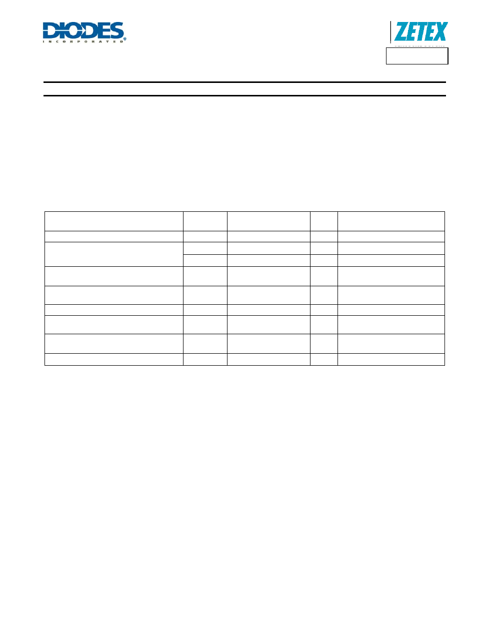
Table 2
Conditions monitored, the method of detection and the nominal STATUS output voltage are given in the following table (Note 15):
Warning/Fault Condition
Severity
(Note 16)
Monitored
Parameters
FLAG
Nominal STATUS Voltage
Normal Operation
H 4.5V
Supply Under-Voltage
1
V
AUX
< 5.6V
L 4.5V
2
V
IN
< 5.6V
L 3.6V
Output Current Out of Regulation
(Note 17)
2
V
SHP
outside normal voltage
range
L 3.6V
Driver Stalled with Switch ‘on’, or ‘off’
(Note 18)
2
t
ON
, or t
OFF
> 100µs
L 3.6V
Switch Over-Voltage
3
LX voltage > 60V
L
2.7
Device Temperature Above Maximum
Recommended Operating Value
4
T
J
> +125°C
L 1.8V
Sense Resistor Current I
RS
Above Specified
Maximum
5
V
SENSE
> 0.375V
L 0.9V
Average Switch > 1.5A
5
I
LX
> 1.5A
L 0.9V
Notes:
15. These STATUS pin voltages apply for an input voltage, V
IN
, of 7.5V < V
IN
< 60V. Below 7.5V the STATUS pin voltage levels reduce and therefore may
not report the correct status. For 6.3V < V
IN
< 7.5V the flag pin still reports an error by going low. At low V
IN
in Boost and Buck-boost modes an over-
current status may be indicated when operating at high boost ratios -– this due to the feedback loop increasing the sense voltage.
16. Severity 1 denotes lowest severity.
17. This warning will be indicated if the output power demand is higher than the available input power; the loop may not be able to maintain regulation.
18. This warning will be indicated if the gate pin stays at the same level for greater than 100µs (e.g. the output transistor cannot pass enough current
to reach the upper switching threshold).