Advanced instruments inc, Gas connections, Electrical connections – Analytical Industries GPR-2800 AIS ATEX Oxygen Analyzer User Manual
Page 12
Advanced Instruments Inc.
12
Gas Connections
The GPR-2800AIS with its standard flow through configuration is designed for positive pressure samples and requires
connections for incoming sample and outgoing vent lines. Zero and span inlet ports are offered as part of the optional sample
systems. The user is responsible for calibration gases and the required components, see below.
Flow rates of 1-5 SCFH cause no appreciable change in the oxygen reading. However, flow rates above 5 SCFH generate
backpressure and erroneous oxygen readings because the diameter of the integral tubing cannot evacuate the sample gas at
the higher flow rate. A flow indicator with an integral metering valve upstream of the sensor is recommended as a means of
controlling the flow rate of the sample gas. A flow rate of 2 SCFH or 1 liter per minute is recommended for optimum
performance.
Caution: Do not place your finger over the vent (it pressurizes the sensor) to test the flow indicator when gas is flowing to the
sensor. Removing your finger (the restriction) generates a vacuum on the sensor and may damage the sensor (voiding the
sensor warranty).
Procedure:
1. Caution: Do not change the factory setting until instructed to do in this manual.
2. Designate one of the bulkhead tube fittings as the VENT and the other SAMPLE.
3. Regulate the pressure as described in Pressure and Flow above.
4. Connect a 1/8” vent line to the compression fitting to be used for venting the sample.
5. Connect a 1/8” ZERO, SPAN or SAMPLE line to the fitting designated SAMPLE.
6. If equipped with optional fittings and/or sample system, connect the ZERO and SPAN gas lines.
7. Allow gas to flow through the transmitters and set the flow rate to 2 SCFH.
8. Note: If equipped with the optional H2S sample conditioning system: Regulate the pressure so that it does not exceed
30 psig use ¼” tubing to make the appropriate connections as labeled on the sample panel.
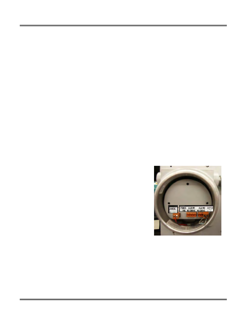
Electrical Connections
Incoming power, power failure and set point alarm, and, output connections are
made to a terminal block mounted on a PCB located in the lower explosion proof
enclosure.
The PCB also includes a transformer to power the alarm relays and intrinsic
safety barriers that limited the amount of voltage going to the upper electronics
enclosure. With proper insulation of the incoming power (see Appendix A), this
configuration the GPR-2800AIS meets the intrinsic safety standards for use in
Class 1, Division 1, Groups A-D hazardous areas.
Caution: The integral 4-20mA converter is internally powered and does not
require external power. DO NOT supply any voltage to either of the two
terminals of the 4-20mA output or the 4-20mA converter will be damaged.
To assure proper grounding, connect the 4-20mA signal output to the external device (PLC, DCS, etc.) before attempting any
zero or span adjustments.
Procedure:
Power requirements consist of a two wire shielded cable and a 12-28V DC with negative ground power supply.
1. Unscrew the cone shaped cover from the lower enclosure.
2. Separate the shielding from the wires of the cable.
3. Ensure the positive and negative terminals of the power supply are connected to the appropriate terminals of the barrier
strip as marked.
4. Connect the shielding of the cable to the ground screw inside the enclosure. Note: The terminals snap together, making it
possible to detach the section with the ground, install the shielded cable and reinstall.
5. Replace the cover.