Asus N4L-VM DH User Manual
Page 27
A S U S N 4 L - V M D H
A S U S N 4 L - V M D H
A S U S N 4 L - V M D H
A S U S N 4 L - V M D H
A S U S N 4 L - V M D H
2 - 5
2 - 5
2 - 5
2 - 5
2 - 5
I n t e r n a l c o n n e c t o r s
I n t e r n a l c o n n e c t o r s
I n t e r n a l c o n n e c t o r s
I n t e r n a l c o n n e c t o r s
I n t e r n a l c o n n e c t o r s
P a g e
P a g e
P a g e
P a g e
P a g e
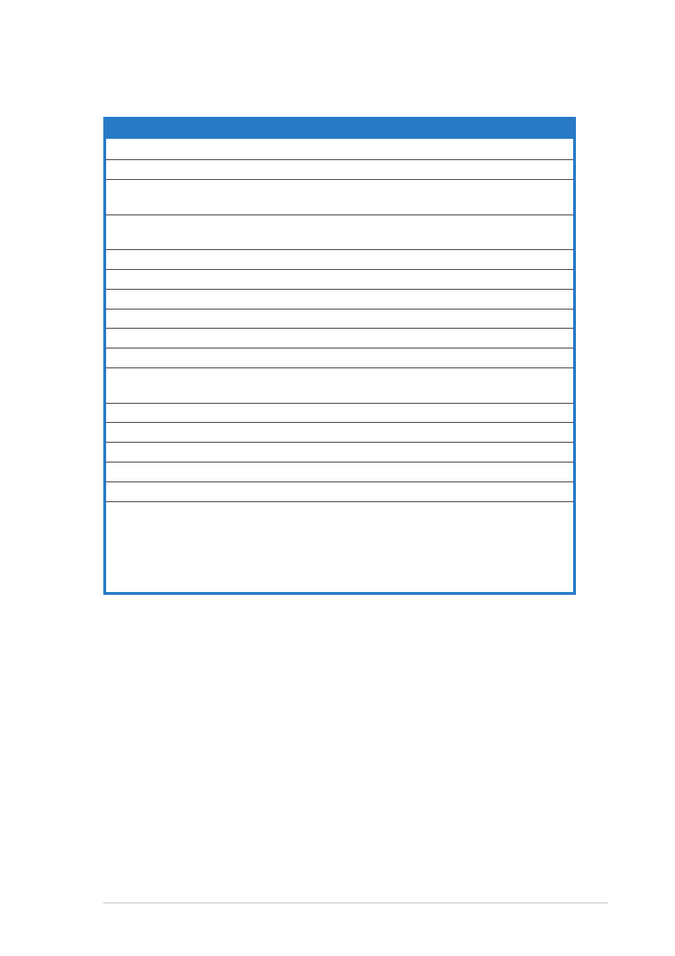
1.
Floppy disk drive connector (34-1 pin FLOPPY)
2-26
2.
IDE connector (40-1 pin IDE)
2-26
3.
Intel
®
ICH7-M DH Southbridge Serial ATA connectors
2-27
(7-pin SATA0 [black], SATA2 [black])
4.
JMicron Serial ATA 3.0 Gb/s RAID connector
2-28
(7-pin SATA_RAID1 [red])
5.
CD audio in connector (4-pin CD)
2-28
6.
USB connectors (10-1 pin USB56, USB78)
2-29
7.
Front panel audio connector (10-1 pin AAFP)
2-30
8.
IEEE 1394a port connector (10-1 pin IE1394_2)
2-30
9.
GAME/MIDI port connector (16-1 pin GAME)
2-31
10.
Serial port connector (10-1 pin COM1)
2-31
11.
CPU and chassis fan connectors
2-32
(3-pin CPU_FAN, 3-pin CHA_FAN)
12.
Chassis intrusion connector (4-1 pin CHASSIS)
2-32
13.
ATX power connectors (24-pin EATXPWR, 4-pin ATX12V)
2-33
14.
Parallel port connector (26-1 pin LPT)
2-34
15.
S/PDIF In/Out connector (6-1 pin SPDIF)
2-35
16.
TV Out connector (6-1 pin TV_C)
2-35
17.
System panel connector (20-pin PANEL)
2-36
•
System power LED (Green 3-pin PLED)
•
Hard disk drive activity LED (Red 2-pin IDE_LED)
•
System warning speaker (Orange 4-pin SPEAKER)
•
ATX power button/soft-off button (Light green 2-pin PWR)
•
Reset button (Blue 2-pin RESET)