Power requirements table – Asus N4L-VM DH User Manual
Page 56
2 - 3 4
2 - 3 4
2 - 3 4
2 - 3 4
2 - 3 4
C h a p t e r 2 : H a r d w a r e i n f o r m a t i o n
C h a p t e r 2 : H a r d w a r e i n f o r m a t i o n
C h a p t e r 2 : H a r d w a r e i n f o r m a t i o n
C h a p t e r 2 : H a r d w a r e i n f o r m a t i o n
C h a p t e r 2 : H a r d w a r e i n f o r m a t i o n
•
We recommend that you use a PSU with a higher power output when
configuring a system with more power consuming devices.
•
Different PCI-E x16 Graphics card requires different +12V_V1
power. To support a high-end PCI-E x16 Graphics card, make sure
that the PSU can provide more 12V power on the 12V_V1 lead."
Power requirements table
Power requirements table
Power requirements table
Power requirements table
Power requirements table
H e a v y
H e a v y
H e a v y
H e a v y
H e a v y
N o r m a l
N o r m a l
N o r m a l
N o r m a l
N o r m a l
L i g h t
L i g h t
L i g h t
L i g h t
L i g h t
CPU
Intel® Core™ Duo
Intel® Core™ Duo
Intel® Core™ Duo
T2600 processor
T2600 processor
T2600 processor
(Dual-Core 2.16 GHz)
(Dual-Core 2.16 GHz) (Dual-Core 2.16
GHz)
PCIe16
6600
Onboard Gfx
Onboard Gfx
DDR2-667 DIMMs
2 x 1G
2 x 512M
2 x 512M
SATA IDE
2
2
2
Optical drive
2
2
1
(DVD/CD-ROW)
PCIe1 Card
1
0
0
PCI Card
2
1
1
USB
6
4
1
Required +12V_V1
>= 10 A
>= 5 A
>= 4 A
(24 Pin)
Required +12V_V2
>= 3 A
>= 3 A
>= 3 A
(4 Pin)
Required wattage
>250 W
>= 150W
>= 120W
1 4 .
1 4 .
1 4 .
1 4 .
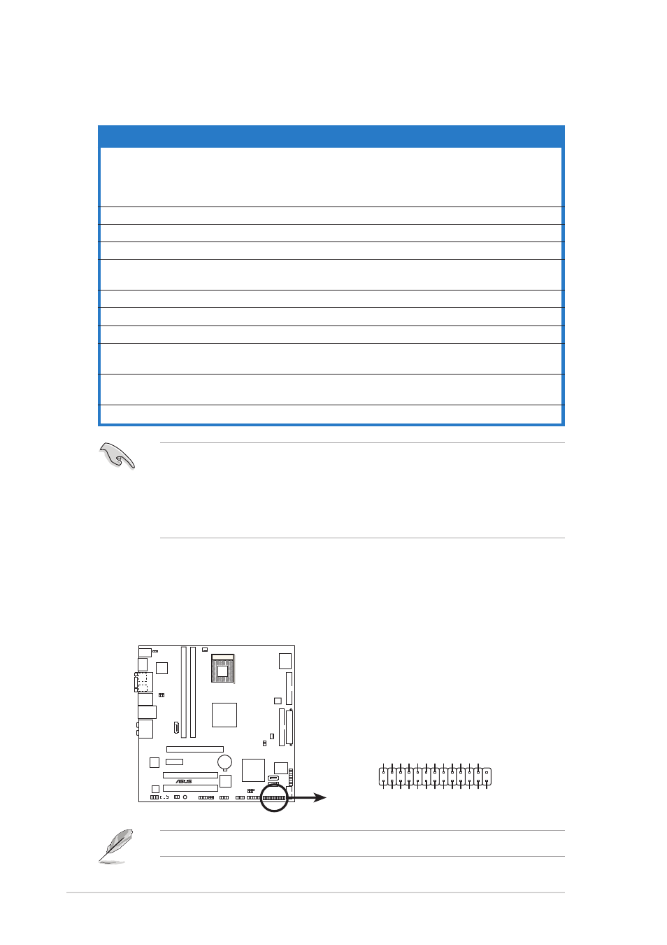
1 4 . Parallel port connector (26-1 pin LPT)
P a r a l l e l p o r t c o n n e c t o r ( 2 6 - 1 p i n L P T )
P a r a l l e l p o r t c o n n e c t o r ( 2 6 - 1 p i n L P T )
P a r a l l e l p o r t c o n n e c t o r ( 2 6 - 1 p i n L P T )
P a r a l l e l p o r t c o n n e c t o r ( 2 6 - 1 p i n L P T )
This connector is for a parallel port. Connect the parallel port module
cable to this connector, then install the module to a slot opening at
the back of the system chassis.
®
N4L-VM DH
N4L-VM DH Parallel port connector
LPT
SPD7
GND
SPD6
GND
SPD5
GND
SPD4
GND
SLCT
PE
GND
BUSY
ACK#
GND
SPD3
GND
SPD2
SLIN#
SPD1
PINIT#
SPD0
ERROR#
STB#
AFD#
GND
Pin 1
The parallel port cable is purchased separately.