Asus N4L-VM DH User Manual
Page 53
A S U S N 4 L - V M D H
A S U S N 4 L - V M D H
A S U S N 4 L - V M D H
A S U S N 4 L - V M D H
A S U S N 4 L - V M D H
2 - 3 1
2 - 3 1
2 - 3 1
2 - 3 1
2 - 3 1
9 .
9 .
9 .
9 .
9 .
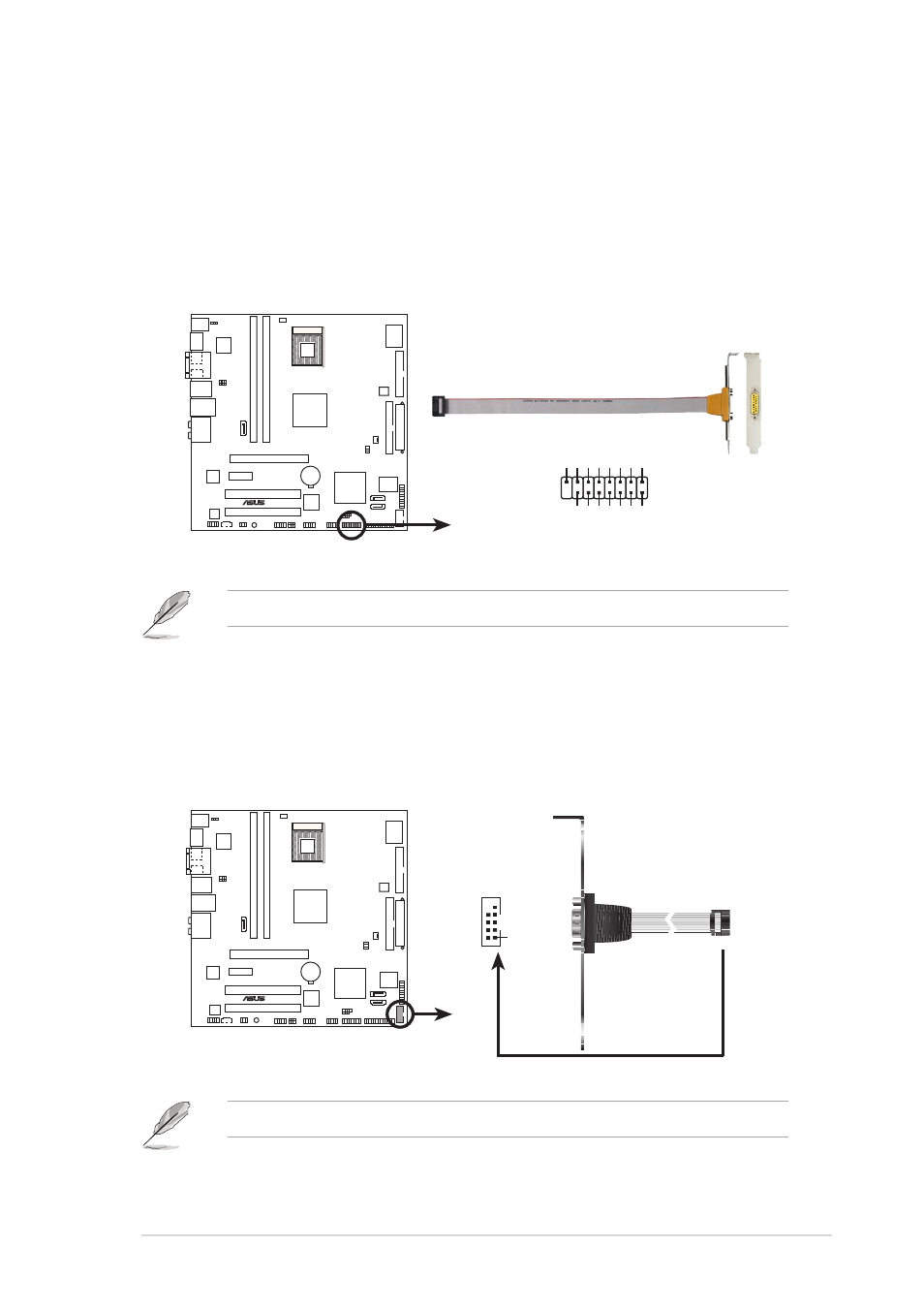
G A M E / M I D I p o r t c o n n e c t o r ( 1 6 - 1 p i n G A M E )
G A M E / M I D I p o r t c o n n e c t o r ( 1 6 - 1 p i n G A M E )
G A M E / M I D I p o r t c o n n e c t o r ( 1 6 - 1 p i n G A M E )
G A M E / M I D I p o r t c o n n e c t o r ( 1 6 - 1 p i n G A M E )
G A M E / M I D I p o r t c o n n e c t o r ( 1 6 - 1 p i n G A M E )
This connector is for a GAME/MIDI port. Connect the USB/GAME or
GAME/MIDI module cable to this connector, then install the module to
a slot opening at the back of the system chassis. The GAME/MIDI port
connects a joystick or game pad for playing games, and MIDI devices
for playing or editing audio files.
1 0 .
1 0 .
1 0 .
1 0 .
1 0 . Serial port connector (10-1 pin COM1)
S e r i a l p o r t c o n n e c t o r ( 1 0 - 1 p i n C O M 1 )
S e r i a l p o r t c o n n e c t o r ( 1 0 - 1 p i n C O M 1 )
S e r i a l p o r t c o n n e c t o r ( 1 0 - 1 p i n C O M 1 )
S e r i a l p o r t c o n n e c t o r ( 1 0 - 1 p i n C O M 1 )
This connector is for a serial (COM) port. Connect the serial port
module cable to this connector, then install the module to a slot
opening at the back of the system chassis.
The GAME/MIDI module is purchased separately.
The serial port module is purchased separately.
®
N4L-VM DH
N4L-VM DH Game connector
GAME
+5V
+5V
J2B1
J2CX
MIDI_OUT
J2CY
J2B2
MIDI_IN
J1B1
J1CX
GND
GND
J1CY
J1B2
+5V
®
N4L-VM DH
N4L-VM DH Serial port2 connector
PIN 1
COM1