Asus N4L-VM DH User Manual
Page 52
2 - 3 0
2 - 3 0
2 - 3 0
2 - 3 0
2 - 3 0
C h a p t e r 2 : H a r d w a r e i n f o r m a t i o n
C h a p t e r 2 : H a r d w a r e i n f o r m a t i o n
C h a p t e r 2 : H a r d w a r e i n f o r m a t i o n
C h a p t e r 2 : H a r d w a r e i n f o r m a t i o n
C h a p t e r 2 : H a r d w a r e i n f o r m a t i o n
8 .
8 .
8 .
8 .
8 .
I E E E 1 3 9 4
I E E E 1 3 9 4
I E E E 1 3 9 4
I E E E 1 3 9 4
I E E E 1 3 9 4a
aa
aa p o r t
p o r t
p o r t
p o r t
p o r t connector
c o n n e c t o r
c o n n e c t o r
c o n n e c t o r
c o n n e c t o r (10-1 pin IE1394_
(10-1 pin IE1394_
(10-1 pin IE1394_
(10-1 pin IE1394_
(10-1 pin IE1394_2
2
2
2
2 )))))
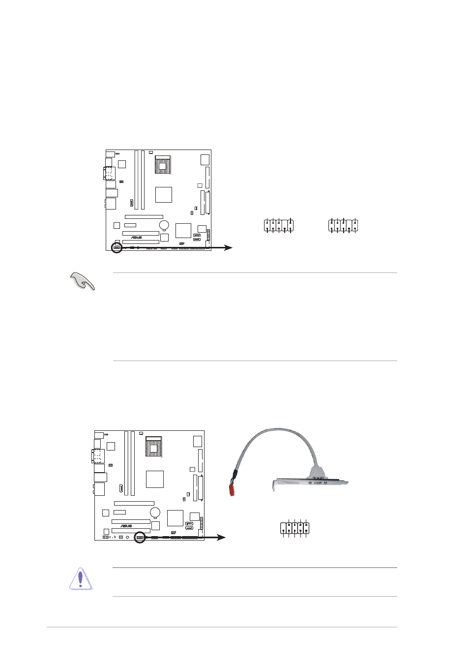
This connector is for the IEEE 1394a port. Connect the IEEE 1394
module cable to this connector, then install the module to a slot
opening at the back of the system chassis.
Never connect a U S B c a b l e
U S B c a b l e
U S B c a b l e
U S B c a b l e
U S B c a b l e to the IEEE 1394a connectors.
Doing so will damage the motherboard!
7 .
7 .
7 .
7 .
7 .
F r o n t p a n e l a u d i o c o n n e c t o r ( 1 0 - 1 p i n A A F P )
F r o n t p a n e l a u d i o c o n n e c t o r ( 1 0 - 1 p i n A A F P )
F r o n t p a n e l a u d i o c o n n e c t o r ( 1 0 - 1 p i n A A F P )
F r o n t p a n e l a u d i o c o n n e c t o r ( 1 0 - 1 p i n A A F P )
F r o n t p a n e l a u d i o c o n n e c t o r ( 1 0 - 1 p i n A A F P )
This connector is for a chassis-mounted front panel audio I/O module
that supports either HD Audio or legacy AC ‘97 audio standard.
Connect one end of the front panel audio I/O module cable to this
connector.
•
We recommend that you connect a high-definition front panel audio
module to this connector to avail of the motherboard’s
high-definition audio capability.
•
By default, this connector is set to legacy AC`97 audio. If you want
to connect a high-definition front panel audio module to this
connector, set the F r o n t P a n e l S u p p o r t T y p e
F r o n t P a n e l S u p p o r t T y p e
F r o n t P a n e l S u p p o r t T y p e
F r o n t P a n e l S u p p o r t T y p e
F r o n t P a n e l S u p p o r t T y p e item in the BIOS
setup to [Azalia]. See page 4-24 for details.
®
N4L-VM DH
N4L-VM DH Analog front panel connector
AAFP
Legacy AC’97
compliant definition
Azalia
compliant definition
SENSE2_RETUR
POR
T1 L
POR
T2 R
POR
T2 L
SENSE1_RETUR
SENSE_SEND
POR
T1 R
PRESENCE#
GND
BLINE_OUT_L
MIC2
Line out_R
Line out_L
BLINE_OUT_R
NC
MICPWR
+5V
A
AGND
®
N4L-VM DH
N4L-VM DH IEEE 1394 connector
IE1394_2
1
GND
+12V
TPB1-
GND
TP
A1-
+12V
TPB1+
GND
TP
A1+