Hardware setup, 37 asus cua user’s manual – Asus CUA User Manual
Page 37
37
ASUS CUA User’s Manual
3. HARDWARE SETUP
3. H/W SETUP
Connectors
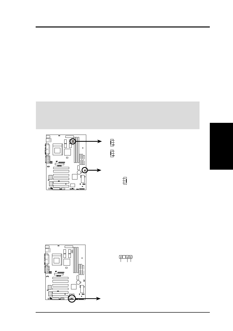
14) IC Power Supply (IC_PWR_FAN), CPU (CPU_FAN),
Chassis (CHA_FAN) Fan Connectors (3 pins)
These connectors support cooling fans of 350mA (4.2 Watts) or less. Orientate
the fans so that the heat sink fins allow airflow to go across the onboard heat
sink(s) instead of the expansion slots. Depending on the fan manufacturer, the
wiring and plug may be different. The red wire should be positive, while the
black should be ground. Connect the fan’s plug to the board taking into consid-
eration the polarity of the connector.
NOTE: The “Rotation” signal is to be used only by a specially designed fan with
rotation signal. The Rotations per Minute (RPM) can be read directly from the
ASUS iPanel or monitored using a utility such as ASUS PC Probe or Intel LDCM.
WARNING!
The CPU and/or motherboard will overheat if there is no airflow
across the CPU and onboard heatsinks. Damage may occur to the motherboard
and/or the CPU fan if these pins are incorrectly used. These are not jumpers,
do not place jumper caps over these pins.
CUA 12-Volt Cooling Fan Power
CPU_FAN
IC_PWR_FAN
GND
Rotation
+12V
CHA_FAN
GND
Rotation
+12V
CUA
®
GND
Rotation
+12V
15) Chassis Intrusion Lead (4-pin CHASSIS)
This requires an external detection mechanism such as a chassis intrusion moni-
tor/sensor or microswitch. The sensor is triggered when a high level signal is
sent to the Chassis Signal lead, which occurs when a panel switch or light detec-
tor is triggered. This function requires the optional ASUS CIDB chassis intru-
sion module to be installed (see 7. APPENDIX). If the chassis intrusion lead is
not used, a jumper cap must be placed over the pins to close the circuit.
CUA Chassis Open Alarm Lead
CUA
®
+5V
olt
(Power Supply Stand By)
Ground
Chassis Signal
CHASSIS
1