The product in operation – OSRAM POWERTRONIC PT-FIT I ECG for HID lamps, with cable clamp User Manual
Page 30
THE PRODUCT IN OPERATION
2.4.5. Installation space for independent devices
POWERTRONIC
®
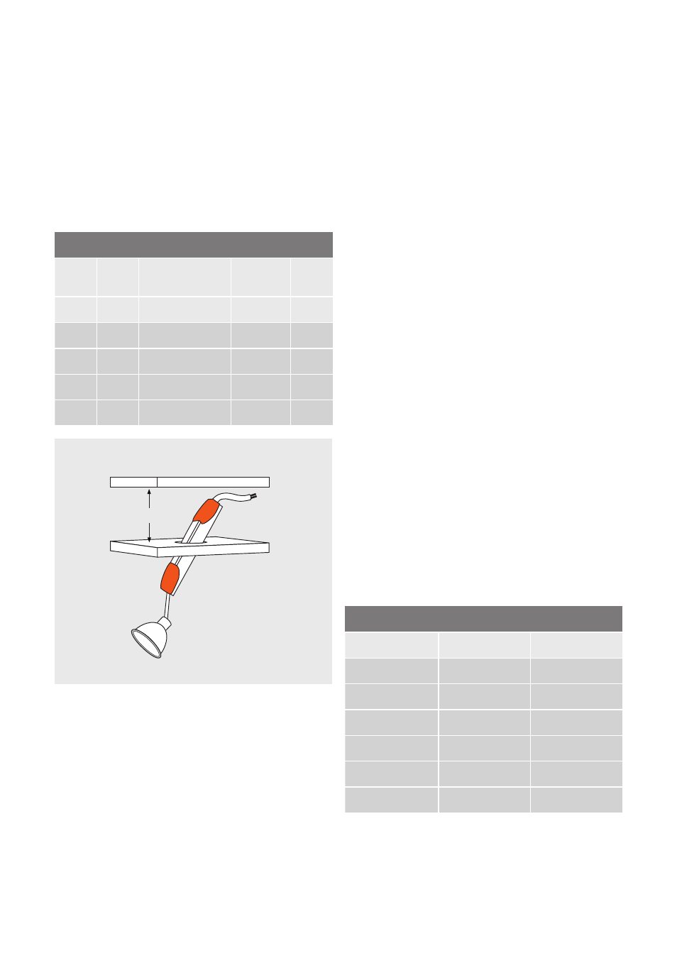
PTi/PT-FIT I devices with integrated
cable clamp are ideal for use in suspended ceilings. In
such applications the diameter of the ceiling cut-out
depends on the installation height available.
The following table gives an overview of the ceiling cut-out
required as a function of the installation depth of the vari-
ous devices with cable clamp.
To ensure optimal thermal isolation, independent devices
should be positioned at a suffi cient distance (> 30 cm)
from the luminaire.
2.4.6. Plug-&-Play installation with cable/socket system
Especially in the project sector, the use of plug-in cable
systems is always preferred. Such Plug-&-Play solutions
offer the following benefi ts:
• Quick and easy connection of the ECG with the luminaire
and of the mains to the ECG
• A coded plug-in system reduces polarity errors in the
installation
• The wiring for the ECG has been factory tested
The polarity must be kept in mind especially for E26/E27 and
E40 screw bases.
30
Indicative details for devices in suspended ceilings
PTi 20 I
PTi 35 to 70 I
PT-FIT 35 to 70 I
PTi 35 to 70 SNAP
PTi 2x35 I
PTi 2x70 I
PTi 100 I
PTi 150 I
∅ (mm)
h (mm)
95
65
80
x
140
104
55
70
110
105
125
40
55
75
70
145
35
45
65
60
Examples of socket types
Socket type
Lamp type
Lamp designation
G12/G22
Pin base lamp
HCI-T, HQI-T
G8.5
Pin base lamp
HCI-TC
Rx7s/Fc2
2-sided socketed lamp
HCI-TS, HQI-TS
E26/E27/E40
(suitable for high voltage)
Screw base
HCI-PAR, HCI-TT,
HCI-ET, HCI-E/P
GU 6.5, GU 8.5
Bayonet base
HCI-TF, HCI-TX/P
GX 8.5, GX 10
Twist and Lock
HCI-R111
Figure 33: Schematic diagram of the installation space for indepen-
dent devices
OSRAM provides the following Plug-&-Play solutions:
• PTi SNAP (with integrated connectors)
• PTi I/P and PT-FIT I/P (prefabricated lamp cable with plug)
• PTi I/2P and PT-FIT I/2P (prefabricated lamp and mains
cable with plugs)
To ensure that the installation of the cable plug-in system
is quick, reliable and, most importantly, safe, the following
tests are carried out by OSRAM as part of prefabrication:
• High-voltage test
• Insulation test
• Function test
2.4.7. Passing network cabling through via "fl oating"
terminal
Due to their generously sized terminal compartment, inde-
pendent POWERTRONIC
®
ECGs with cable clamp allow
the use of a terminal (e.g. a Wago terminal) to pass the
mains cable from one device to the next. In order to use
this option it should be kept in mind that the cable tempe-
ratures must not exceed the maximum permissible levels
in the ECG.
2.4.8. Lamp sockets that may be used
In principle, all sockets that conform to the requirements
for high-voltage can be used to operate the appropriate
lamps with a POWERTRONIC
®
ECG. Generally, an ignition
voltage of up to 4.5 kV can occur. Further details can be
found on the stamp of the relevant ECG or in its technical
information sheet.
When connecting the socket (or the luminaire) to the ECG
it is essential to ensure that Lamp High and Lamp Low, i.e.
the ignition cables with high and low potential respectively,
are correctly connected.
The following list indicates the most commonly used sock-
ets for metal halide lamps suitable to be operated by the
ECG:
h