Wiring and configuration of the ecg – OSRAM OPTOTRONIC Constant current LED power supplies with 3DIM User Manual
Page 13
13
WIRING AND CONFIGURATION OF THE ECG
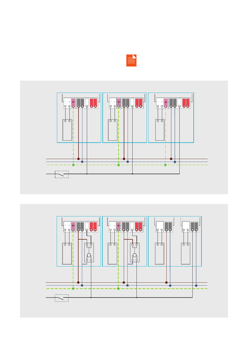
Figure 18a shows the setup if only 3DIM ECGs are con-
nected to the SD control switch. In case other ballasts
or loads are supplied via the SD line (e.g. L2) or an exter-
nal surge protection device is connected to this port, an
additional relay needs to be used within each luminaire
(see fi gure 18b), unless something different is mentioned
in the product- related documents (data sheet or instruc-
tion sheet). The used relay should be suitable for low
switching currents < 1 mA (mostly gold plated contacts).
The SD control switch shown in fi gures 18a/b can be a re-
lay connected to a timer with a remote HIGH/LOW voltage
signal.
For details, please refer to the 3DIM Tool manual.
Figure 18a: StepDIM activation for a group of 3DIM ECGs by the same control switch (example).
Figure 18b: StepDIM port set-up inside luminaire for mixed installation (Phase L2 is used to activate SD and also to supply other ballasts or loads).
Luminaire 1
Luminaire 1
Depending on
the ECG type
Depending on
the ECG type
3DIM ECG
3DIM ECG
Relay
Relay
LED out
LED out
L
L
L
L
L
N
N
N
N
N
SD
SD
SD
SD
SD
DA
DA
DA
DA
DA
DA
DA
DA
DA
DA
LED out
LED out
LED out
3DIM ECG
3DIM ECG
3DIM ECG
ECG 1
ECG 2
Depending on
the ECG type
Depending on
the ECG type
Depending on
the ECG type
Light
load
Light
load
Light
load
Light
load
Light
load
Light
load
Light
load
Luminaire 2
Luminaire 2
Luminaire 3
Luminaire 3
SD
control switch
SD
control switch
L1
L1
N
N
L2
L2
PE
PE