Ocean Optics Nirquest Install User Manual
Page 46
B: Specifications
40
016-700000-000-02-201301
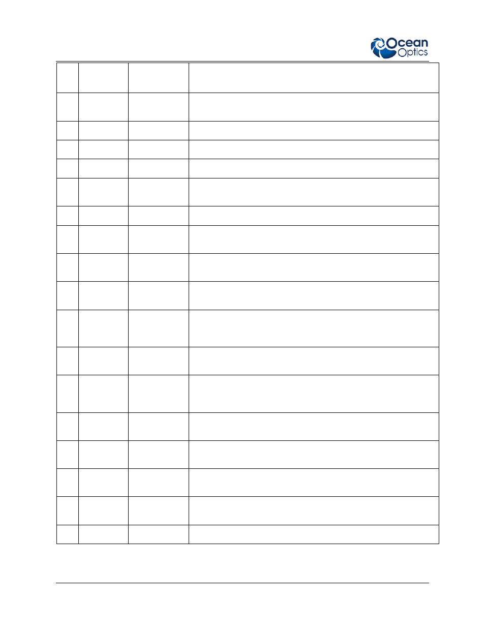
Pin
#
Function
Input/Output
Description
3
GPIO (2)
Input/Output
General purpose software-programmable, digital input/output
(channel number)
4
N/A
N/A
Reserved
5
Ground
Input/Output
Ground
6
I
2
C SCL
Input/Output
I
2
C clock signal for communication to other I
2
C peripherals
7
GPIO (0)
Input/Output
General purpose software-programmable, digital input/output
(channel number)
8
I
2
C SDA
Input/Output
I
2
C data signal for communication to other I
2
C peripherals
9
GPIO (1)
Input/Output
General purpose software-programmable, digital input/output
(channel number)
10
Ext.
Trigger In
Input
TTL input trigger signal
11
GPIO (3)
Input/Output
General purpose software-programmable, digital input/output
(channel number)
12
V
CC
or 5V
IN
Input or
Output
Input power pin for NIRQuest – When operating via USB, this pin
can power other peripherals – Ensure that peripherals comply with
USB specifications (no TEC power)
13
SPI Data
Out
Output
SPI Master Out Slave In (MOSI) signal for communication to other
SPI peripherals
14
V
CC
or 5V
IN
Input or
Output
Input power pin for NIRQuest – When operating via USB, this pin
can power other peripherals – Ensure that peripherals comply with
USB specifications (no TEC power)
15
SPI Data In Input
SPI Master In Slave Out (MISO) signal for communication to other
SPI peripherals
16
GPIO (4)
Input /Output
General purpose software-programmable, digital input/output
(channel number)
17
Single
Strobe
Output
TTL output pulse used as a strobe signal – Has a programmable
delay relative to the beginning of the spectrometer integration period
18
GPIO (5)
Input/Output
General purpose software-programmable, digital input/output
(channel number)
19
SPI Clock
Output
SPI clock signal for communication to other SPI peripherals