Ocean Optics QE Pro Install User Manual
Page 32
B: Specifications
26
891-00000-000-02-201401
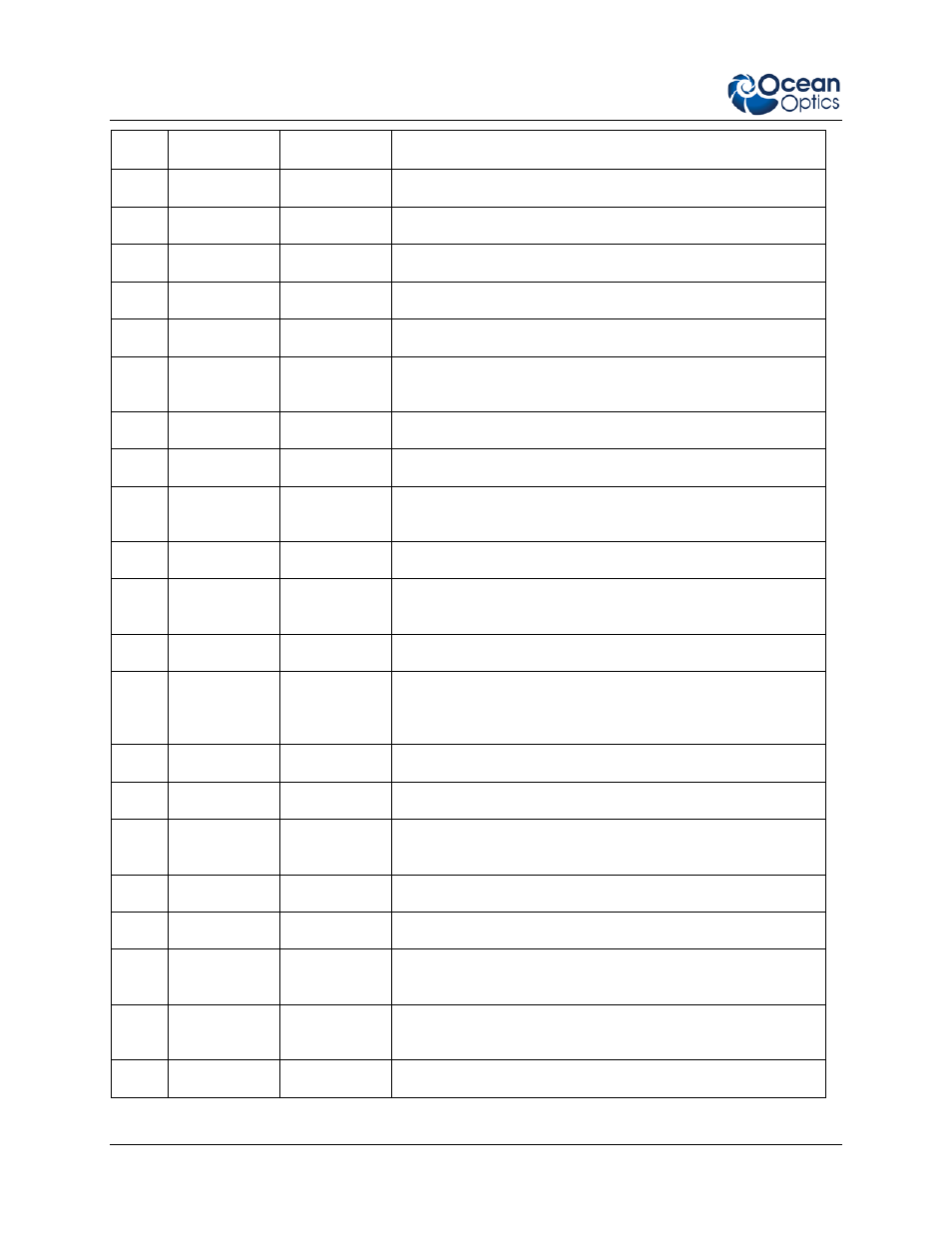
Pin # Function
Input/Output
Description
5
Ground
Input/Output
Ground
6
I2C SCL
Input/Output
I2C clock signal for communication to other I2C peripherals
7
GPIO (0)
Input/Output
General Purpose Input Output
8
I2C SDA
Input/Output
I2C data signal for communication to other I2C peripherals
9
GPIO (1)
Input/Output
General Purpose Input Output
10
Ext. Trigger
In
Input
CMOS input trigger tolerant from 3-5V
11
GPIO (3)
Input/Output
General Purpose Input Output
12
VOUT
Output
Output power pin for QE Pro
13
SPI_MOSI
Output
SPI Master Out Slave In (MOSI) signal for communication to
other SPI peripherals
14
VOUT
Output
Output power pin for QE Pro
15
SPI MISO
Input
SPI Master In Slave Out (MISO) signal for communication to
the other SPI peripherals
16
GPIO (4)*
Input /Output
General Purpose Input Output
17
Single Strobe Output
CMOS (3.3V) output pulse used as a strobe signal – Has a
programmable delay relative to the beginning of the
spectrometer integration period
18
GPIO (5)
Input/Output
General Purpose Input Output
19
SPI Clock
Output
SPI clock signal for communication to other SPI peripherals
20
Continuous
Strobe
Output
CMOS output signal used to pulse a strobe – Divided down
from the master clock signal
21
SPI CS
Output
External SPI chip select (active low)
22
GPIO (6)
Input/Output
General Purpose Input Output
23
RESET
Input
This pin is pulled up to 5V by a 10K internal resistor. Pull
down to ground to reset. Leave open for normal operation.
24
RS-232 CTS
Output
RS-232 Clear to Send control logic signal – used to enable
or suspend host transmission to the QE Pro
25
Lamp Enable
Output
CMOS signal driven Active HIGH when the Lamp Enable