Pin accessory connector pinout diagram – Ocean Optics QE Pro Install User Manual
Page 31
B: Specifications
891-00000-000-02-201401
25
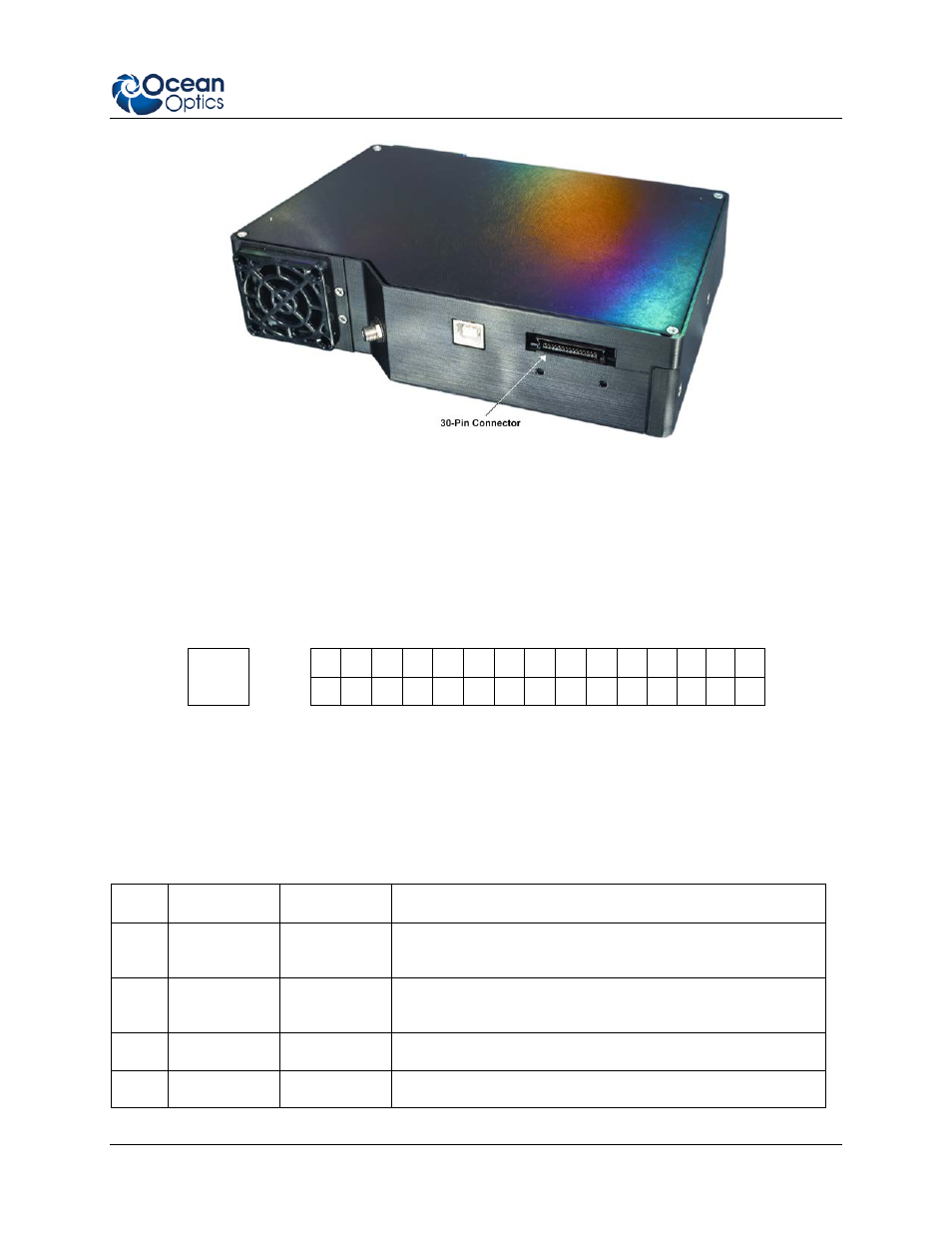
Location of QE Pro 30-Pin Accessory Connector
30-Pin Accessory Connector Pinout Diagram
When facing the 30-pin Accessory Connector on the front of the vertical wall of the QE Pro, pin
numbering is as follows:
USB
Port
2
4
6
8
10
12
14
16
18
20
22
24
26
28
30
1
3
5
7
9
11
13
15
17
19
21
23
25
27
29
30-Pin Accessory Connector Pinout Diagram
30-Pin Accessory Connector – Pin Definitions and
Descriptions
The following table contains information regarding the function of each pin in the QE Pro’s 30-Pin
Accessory Connector:
Pin # Function
Input/Output
Description
1
RS232 Rx
Input
RS232 receive signal – Communicates with a PC over DB9
Pin 3
2
RS232 Tx
Output
RS232 transmit signal – Communicates with a PC over DB9
Pin 2
3
GPIO (2)
Input/Output
General Purpose Input Output
4
-
-
Unused
- Apex 785 Raman (1 page)
- STS-UV (2 pages)
- TR2 Engineering Note (4 pages)
- SAD500 Communications and Control (19 pages)
- Red Tide USB650 Install (26 pages)
- Fiber Optic Termination Kit (6 pages)
- Transmissive pH Probe (10 pages)
- Remora (42 pages)
- PlasCalc (59 pages)
- Correcting Device Driver Issues (8 pages)
- ecoVis Krypton Light Source (16 pages)
- LPC-500CM (28 pages)
- HPX-2000 (24 pages)
- ADC1000-USB (27 pages)
- Torus Operating Instructions (30 pages)
- ADC2000-PCI (13 pages)
- Sensors for Real-Time Analysis (2 pages)
- IDRaman reader (2 pages)
- DH-2000-CAL (30 pages)
- QE65 Pro (32 pages)
- Collimating Lenses (2 pages)
- D1000 (2 pages)
- IDRaman mini (2 pages)
- HR2000CG-UV-NIR (42 pages)
- Cool Red (1 page)
- HL-2000 (20 pages)
- XE-1 Xenon (6 pages)
- USB-ADP Serial Adapters (3 pages)
- CHEM2000 (36 pages)
- Deuterium-Halogen Calibration Light Source (19 pages)
- NeoFox Engineering Note (30 pages)
- QE Pro (2 pages)
- OOIBase32 (140 pages)
- AR-1 Argon (6 pages)
- pH Sensor Patches, Probes and Cuvettes (36 pages)
- SpecLine Offline Spectroscopy (60 pages)
- HL-2000-HP-232 (26 pages)
- External Triggering Options Instructions for Spectrometers with Firmware Version 3.0 and Above (16 pages)
- Breakout Box (10 pages)
- USB-ISS-UV_VIS (4 pages)
- ISS-UV_VIS (6 pages)
- OOIColor (14 pages)
- LS-1 Series (12 pages)
- Apex Install (24 pages)
- DH-2000 (34 pages)