Tvs diode arrays, Lightning surge protection - srv05 series, Diodes) – Littelfuse SRV05 Series User Manual
Page 3: Srv05 4 h t g, Pulse waveform capacitance vs. reverse bias, Soldering parameters ordering information, Part numbering system part marking system
© 2013 Littelfuse, Inc.
Specifications are subject to change without notice.
Revised: 11/25/13
TVS Diode Arrays
(SPA
®
Diodes)
Lightning Surge Protection - SRV05 Series
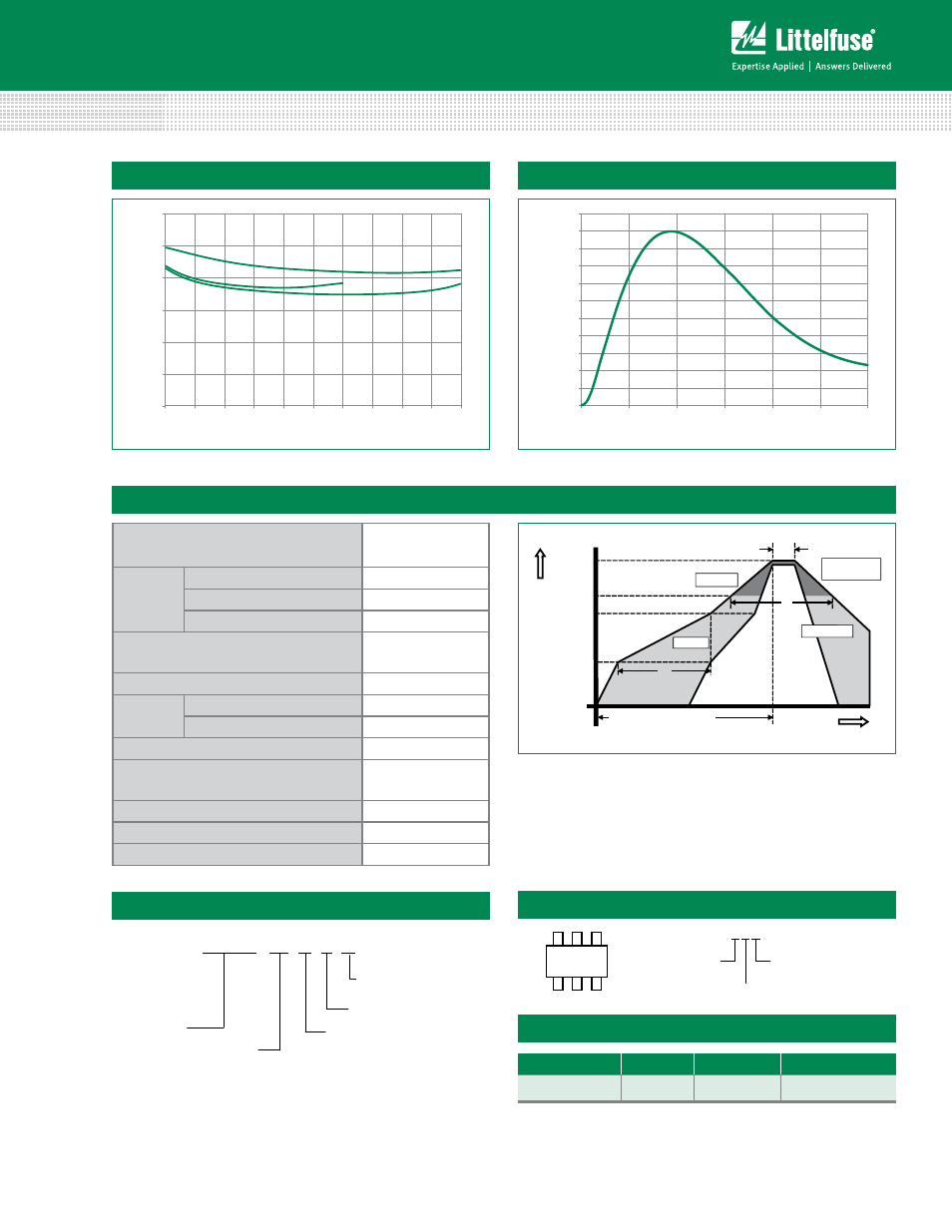
Pulse Waveform
Capacitance vs. Reverse Bias
0.0
0.5
1.0
1.5
2.0
2.5
3.0
0.0 0.5 1.0 1.5 2.0 2.5 3.0 3.5 4.0 4.5 5.0
DC Bias (V)
Capacitance (pF)
V
CC
=Float
V
CC
=5V
V
CC
=3.3V
0%
10%
20%
30%
40%
50%
60%
70%
80%
90%
100%
110%
0.0 5.0 10.0 15.0 20.0 25.0 30.0
Time (μs)
Percent of
I
PP
Time
Te
mperatur
e
T
P
T
L
T
S(max)
T
S(min)
25
t
P
t
L
t
S
time to peak temperature
Preheat
Preheat
Ramp-up
Ramp-up
Ramp-down
Ramp-do
Critical Zone
T
L
to T
P
Critical Zone
T
L
to T
P
Reflow Condition
Pb – Free assembly
Pre Heat
- Temperature Min (T
s(min)
)
150°C
- Temperature Max (T
s(max)
)
200°C
- Time (min to max) (t
s
)
60 – 180 secs
Average ramp up rate (Liquidus) Temp
(T
L
) to peak
3°C/second max
T
S(max)
to T
L
- Ramp-up Rate
3°C/second max
Reflow
- Temperature (T
L
) (Liquidus)
217°C
- Temperature (t
L
)
60 – 150 seconds
Peak Temperature (T
P
)
260
+0/-5
°C
Time within 5°C of actual peak
Temperature (t
p
)
20 – 40 seconds
Ramp-down Rate
6°C/second max
Time 25°C to peak Temperature (T
P
)
8 minutes Max.
Do not exceed
260°C
Soldering Parameters
Ordering Information
Part Number
Package
Marking
Min. Order Qty.
SRV05-4HTG
SOT23-6
L*4
3000
Part Numbering System
Part Marking System
SRV05 4 H T G
Series
Number of
Channels
Package
H: SOT23-6
T= Tape & Reel
G= Green
–
L*4
L * 4
Product Series
L = SRV05
Number of Channels
Assembly Site
(Varies)
L = S
(Varies)