Tvs diode arrays, Lightning surge protection - srv05 series, Diodes) – Littelfuse SRV05 Series User Manual
Page 2
© 2013 Littelfuse, Inc.
Specifications are subject to change without notice.
Revised: 11/25/13
TVS Diode Arrays
(SPA
®
Diodes)
Lightning Surge Protection - SRV05 Series
CAUTION: Stresses above those listed in “Absolute Maximum Ratings” may cause
permanent damage to the device. This is a stress only rating and operation of the device
at these or any other conditions above those indicated in the operational sections of this
specification is not implied.
1
Non-repetitive pulse per waveform on page 3
Absolute Maximum Ratings
Symbol
Parameter
Value
Units
I
PP
Peak Current (t
p
=8/20μs)
1
10
A
P
PK
Peak Pulse Power (t
p
=8/20μs)
150
W
T
OP
Operating Temperature
–40 to 125
°C
T
STOR
Storage Temperature
–55 to 150
°C
Thermal Information
Parameter
Rating
Units
Storage Temperature Range
–55 to 150
°C
Maximum Junction Temperature
150
°C
Maximum Lead Temperature
(Soldering 20-40s)
260
°C
Electrical Characteristics
(T
OP
=25ºC)
Parameter
Symbol
Test Conditions
Min
Typ
Max
Units
Reverse Standoff Voltage
V
RWM
I
R
≤ 1µA
6.0
V
Reverse Voltage Drop
V
R
I
R
= 1mA
8.0
V
Reverse Leakage Current
I
LEAK
V
R
=5V
0.1
0.5
µA
Clamp Voltage
1
V
C
I
PP
=1A, t
p
=8/20µs, I/O to GND
2
8.8
10.0
V
I
PP
=5A, t
p
=8/20µs, I/O to GND
2
11.5
13.0
V
I
PP
=8A, t
p
=8/20µs, I/O to GND
2
13.2
15.0
V
Dynamic Resistance
R
DYN
(V
C2
- V
C1
) / (I
PP2
- I
PP1
)
0.7
Ω
ESD Withstand Voltage
1
V
ESD
IEC61000-4-2 (Contact)
±20
kV
IEC61000-4-2 (Air)
±30
kV
Diode Capacitance
1
C
I/O-GND
Reverse Bias=0V
2.4
3.0
pF
Reverse Bias=1.65V
2.0
pF
Diode Capacitance
1
C
I/O-I/O
Reverse Bias=0V
1.2
pF
Notes:
1
Parameter is guaranteed by design and/or device characterization.
2
Repetitive pulse per waveform on page 3.
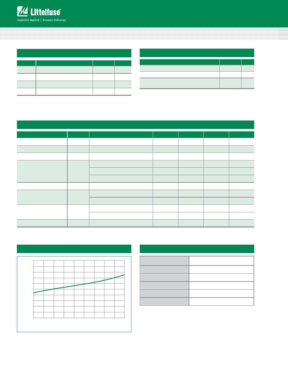
Clamping Voltage vs. I
PP
0.0
2.0
4.0
6.0
8.0
10.0
12.0
14.0
16.0
18.0
20.0
1 2 3 4 5 6 7 8 9 10
Peak Pulse Current-I
PP
(A)
Clamp Voltage (V
C
)
Product Characteristics
Lead Plating
Matte Tin
Lead Material
Copper Alloy
Lead Coplanarity
0.0004 inches (0.102mm)
Substitute Material
Silicon
Body Material
Molded Epoxy
Flammability
UL 94 V-0
Notes :
1. All dimensions are in millimeters
2. Dimensions include solder plating.
3. Dimensions are exclusive of mold flash & metal burr.
4. Blo is facing up for mold and facing down for trim/form, i.e. reverse trim/form.
5. Package surface matte finish VDI 11-13.