Varistor products, Thermally protected varistors > smov25s series – Littelfuse SMOV25S Varistor Series User Manual
Page 5
© 2013 Littelfuse, Inc.
241
Revised: May 8, 2013
Varistor Products
Specifications are subject to change without notice.
Please refer to www.littelfuse.com/series/smov25s.html for current information.
SMOV25S Varistor Series
Thermally Protected Varistors > SMOV25S Series
SMOV
25S
Series
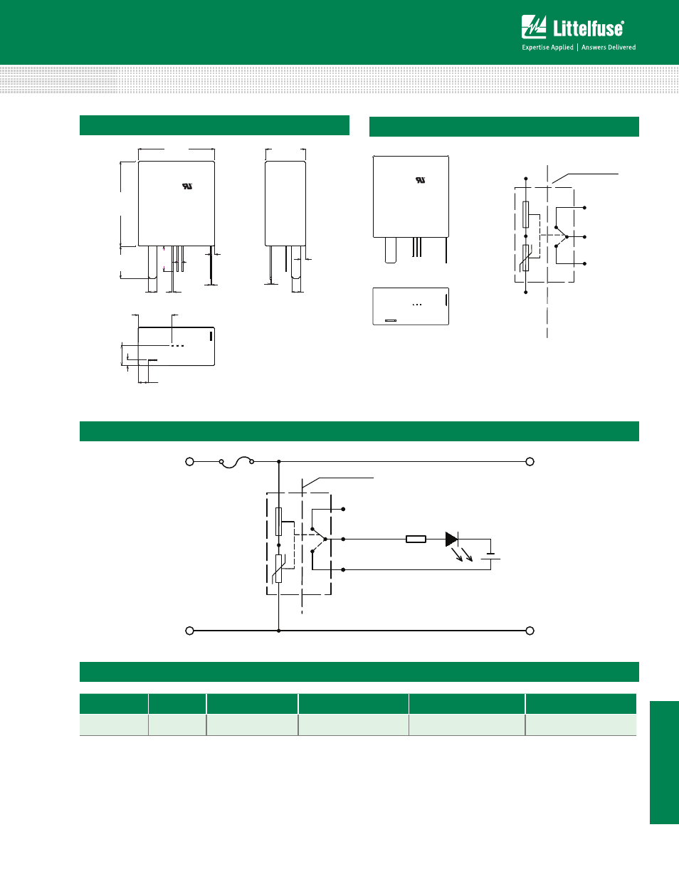
Product Dimensions
31Max
36Max
16.5Max
2±0.3
3.5±0.2
3*0.6±0.2
0.3±0.2
1.3±0.3
9Min
10Min
1.4±0.2
0.5±0.2
8.
5±0.
5
2.
5±0.3
4.0±1.2
13.4±0.2
LF 9
SMOV25S321MP
1148
3.5±0.2
Application Example
Thermal
disconnect
MOV
S1 ON
S3 Common
S2 OFF
P1
P2
Primary side
Secondary side
Galvanic isolation
To
Protected Circuit
Note: EXAMPLE ONLY - Connection to S2-S3 and S1-S3
depends on customer indication circuit and can vary.
R
LED
* LED is off when the product is normal(S1,S3 connected),
LED is on when the product disconect opens(switch change
status; S2,S3 connected as shown by dotted line ).
Thermal
disconnect
MOV
S1 ON
(Normal Close)
S3 Common
S2 OFF
(Normal open)
P1
P2
Primary side
Secondary side
Galvanic isolation
LF9
SMOVXXS321MP
1209
S2 S3 S1
P2
P1
P2
P1
S2 S3 S1
Lead Configuration
SMOV Switch
Voltage DC
Current (Amps)
Contact Resistance Max. Insulation Resistance Min.
Dialectric Strength
0.5mA/Minute
Switch
12V
0.1A
70mΩ
100MΩ
500VAC
Switch Specification