Varistor products, Thermally protected varistors > smov25s series, Peak current & energy derating curve – Littelfuse SMOV25S Varistor Series User Manual
Page 3
© 2013 Littelfuse, Inc.
239
Revised: May 8, 2013
Varistor Products
Specifications are subject to change without notice.
Please refer to www.littelfuse.com/series/smov25s.html for current information.
SMOV25S Varistor Series
Thermally Protected Varistors > SMOV25S Series
SMOV
25S
Series
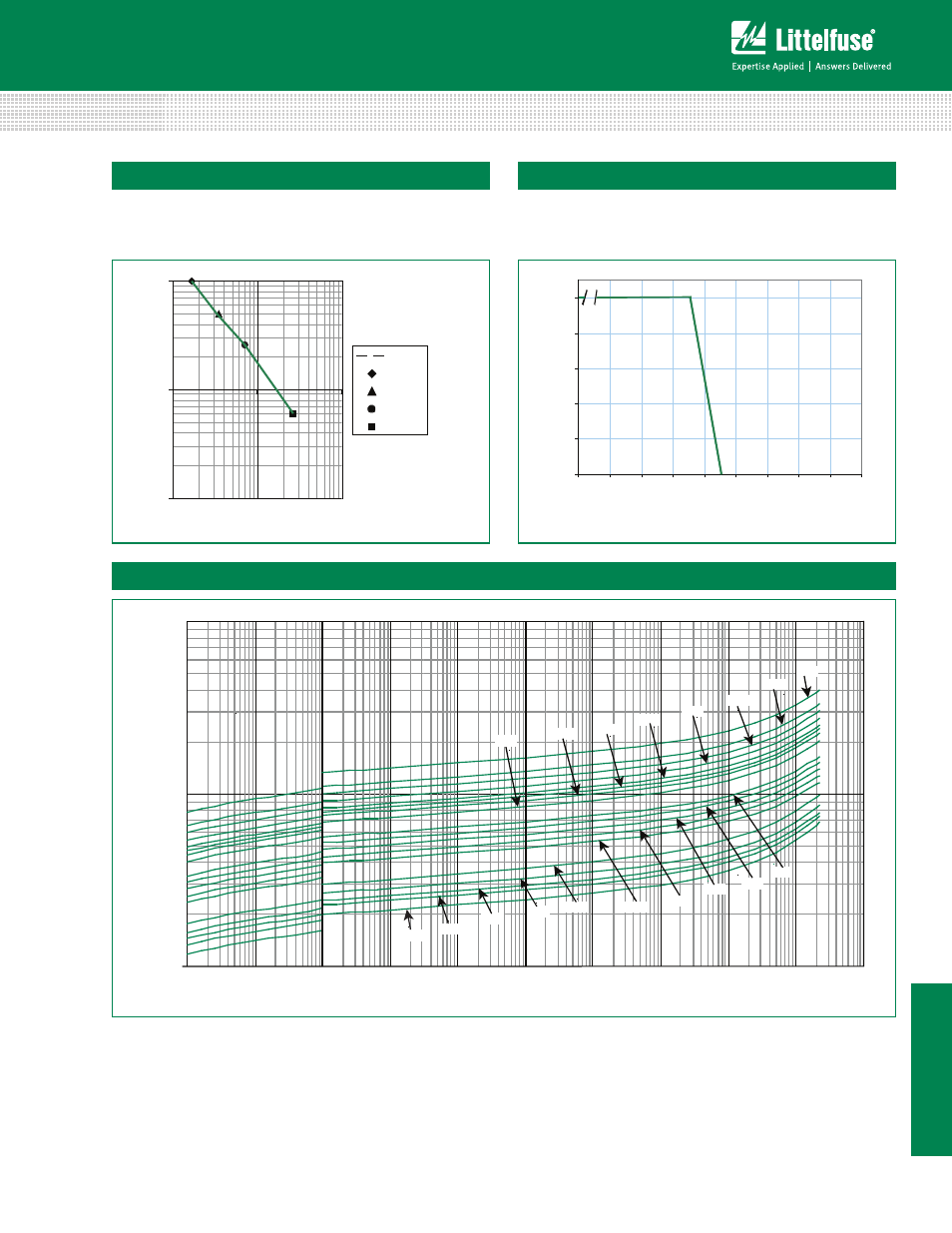
Typical time to open circuit under UL 1449 Abnormal
Overvoltage Limited Current Test:
Thermal Characteristics
0 .1
1
1 0
1
1 0
100
Current (A)
10 A
5 A
2.5 A
0.5 A
Typical
0
20
40
60
80
100
- 45
50
60
70
80
90
100
110
120
130
AMBIENT TEMPERATURE (ºC)
PERCEN
T OF RA
TED
V
ALUE
Peak Current & Energy Derating Curve
100
1000
10000
10μA
100μA
1mA
10mA
100mA
1A
10A
100A
1000A 10000A
100000A
Peak Current
Maximum P
eak
V
oltage (V)
750
625
550
510
460
440
385
420
115
130
140
150
175
230
250
275
300
320
Transient V–I Characteristic Curves
For applications exceeding 75ºC ambient temperature, the
peak surge current and energy ratings must be reduced
as shown below.
Figure 1
Figure 2
Figure 3