Varistor products, Thermally protected varistors > smov25s series, Wave solder profile – Littelfuse SMOV25S Varistor Series User Manual
Page 4: Lead–free profile, Non lead–free profile
© 2013 Littelfuse, Inc.
240
Revised: May 8, 2013
Varistor Products
Specifications are subject to change without notice.
Please refer to www.littelfuse.com/series/smov25s.html for current information.
SMOV25S Varistor Series
Thermally Protected Varistors > SMOV25S Series
Operating/Storage Temp.
-45°C to +75°C / -45°C to +85°C
Passive Aging
+75°C, 1000 hours
-/+10% typical voltage change
Humidity Aging
+75°C, 85%R.H., 1000 hours
-/+10% typical voltage change
Thermal Shock
+75°C to -40°C 5 times
-/+10% typical voltage change
Solvent Resistance
MIL-STD-202, Method 215F
Moisture Sensitivity
Level 1, J-STD-020C
Lead Material
Tin–coated Copper wire
Soldering
Characteristics
Solderability per MIL-STD-202,
Method 208E
Insulating Material
Cured, flame retardant epoxy polymer
meets UL94V-0 requirements
Device Labeling
Marked with LF, voltage, UL logos, and
date code
Physical Specifications
Environmental Specifications
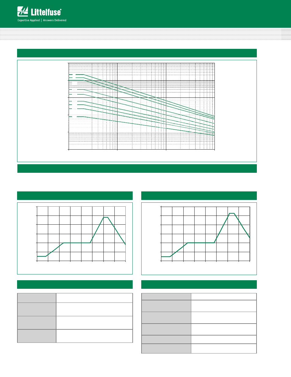
SMOV25S Pulse Rating Curve
1
2
∞
15
10
2
10
3
1
10
100
1000
10000
100000
10
100
1000
10000
Impulse Duration (secs)
10
4
10
5
10
6
Figure 4
Wave Solder Profile
Because the SMOV25S Series varistors contain a thermal protec-
tion device, care must be taken when soldering the devices into
place. Two soldering methods are possible. Firstly, hand soldering:
0
50
100
150
200
250
300
0
0.5
1
1.5
2
2.5
3
3.5
4
TIME(MINUTES)
T
E
M
P
E
RAT
URE
(
ºC)
Maximum Wave 240C
Lead–free Profile
0
50
100
150
200
250
300
0
0.5
1
1.5
2
2.5
3
3.5
4
TIME(MINUTES)
T
EMPER
A
T
U
R
E
(º
C
)
Maximum Wave 260C
Non Lead–free Profile
It is recommended to heat–sink the leads of the device. Secondly,
wave–soldering: It is critically important that all preheat stage and
the solder bath temperatures are rigidly controlled.
Figure 5
Figure 6