Teccor, Brand thyristors, Thermal resistances – Littelfuse Qxx25xx Series User Manual
Page 4
134
Revised: 09/23/13
©2013 Littelfuse, Inc
Specifications are subject to change without notice.
Teccor
®
brand Thyristors
25 Amp Standard & Alternistor (High Commutation) Triacs
Qxx25xx & Qxx25xHx Series
Thermal Resistances
Symbol
Parameter
Value
Unit
R
T(J-C)
Junction to case (AC)
Qxx25R5 / Qxx25N5
Qxx25R6 / Qxx25NH6
Qxx25RH5 / Qxx25NH5
0.89
°C/W
Qxx25P5
1.6
Qxx25L6 / Qxx25LH5
2.0
Qxx25K6 / Qxx25J6
1.32
R
T(J-A)
Junction to ambient
Qxx25Ry
45
°C/W
Qxx25L6 / Qxx25LH5
50
Note: xx = voltage, y = sensitivity
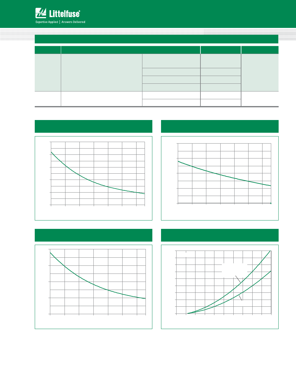
Figure 1: Normalized DC Gate Trigger Current
vs. Junction Temperature
Figure 2: Normalized DC Gate Trigger Voltage
vs. Junction Temperature
0.0
0.5
1.0
1.5
2.0
-40
-15
10
35
60
85
110
125
Junction Temperature (T
J
) -- (ºC)
R
a
ti
o of
V
GT
/ V
GT
(T
J
= 2
5
ºC)
0.0
0.5
1.0
1.5
2.0
2.5
-40
-15
10
35
60
85
110
125
Junction Temperature (T
J
) -- (°C)
R
a
ti
o of
I
GT
/I
GT
(T
J
= 2
5
°C)
Figure 3: Normalized DC Holding Current
vs. Junction Temperature
Figure 4: On-State Current vs. On-State
Voltage (Typical)
0.0
0.5
1.0
1.5
2.0
-40
-15
10
35
60
85
110
125
Junction Temperature (T
J
) -- (ºC)
R
a
ti
o of
I
H
/ I
H
(T
J
= 2
5
ºC)
T
J
= 25°C
0
10
20
30
40
50
60
70
80
90
0.7
0.8
0.9
1.0
1.1
1.2
1.3
1.4
1.5
1.6
1.7
Instantaneous On-state Voltage (v
T
) – Volts
In
stan
tan
e
o
u
s
O
n
-state C
u
rr
e
n
t
(i
T
) –
Am
p
s
Qxx25R5
Qxx25N5
Qxx25P5/Qxx25R6
Qxx25L6/Qxx25NH6
Qxx25K6/Qxx25J6
Qxx25RH5/Qxx25LH5
Qxx25NH5