Tvs diode arrays, General purpose esd protection - sp720 series, Diodes) – Littelfuse SP720 Lead-Free_Green Series User Manual
Page 3
© 2013 Littelfuse, Inc.
Specifications are subject to change without notice.
Revised: 04/24/13
TVS Diode Arrays
(SPA
®
Diodes)
General Purpose ESD Protection - SP720 Series
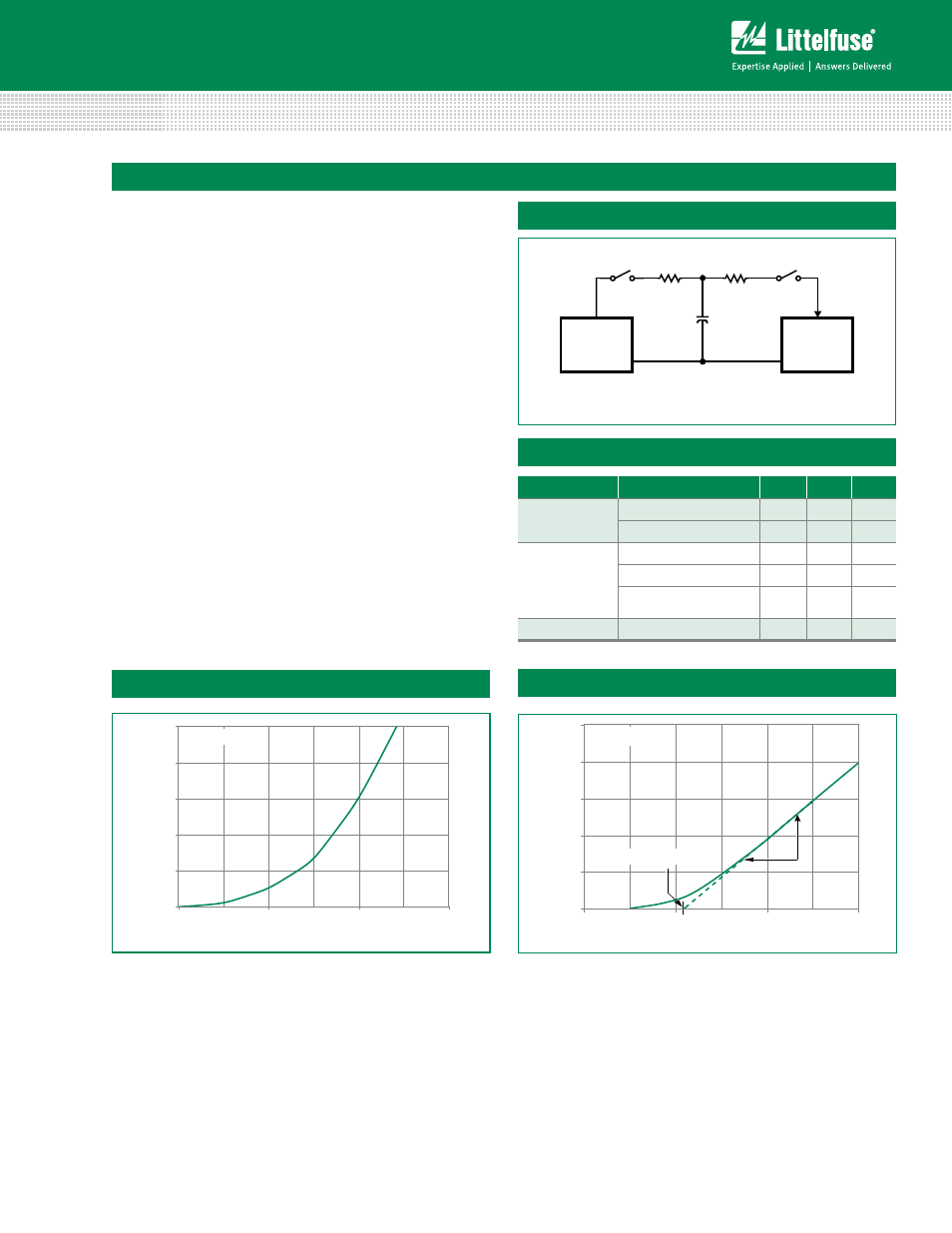
ESD Capability
ESD capability is dependent on the application and defined
test standard. The evaluation results for various test
standards and methods based on Figure 1 are shown in
Table 1.
For the “Modified” MIL-STD-3015.7 condition that is
defined as an “in-circuit” method of ESD testing, the V+
and V- pins have a return path to ground and the SP720
ESD capability is typically greater than 15kV from 100pF
through 1.5kΩ. By strict definition of MIL-STD-3015.7 using
“pin-to-pin” device testing, the ESD voltage capability
is greater than 6kV. The MIL-STD-3015.7 results were
determined from AT&T ESD Test Lab measurements.
The HBM capability to the IEC 61000-4-2 standard is
greater than 15kV for air discharge (Level 4) and greater
than 4kV for direct discharge (Level 2). Dual pin capability (2
adjacent pins in parallel) is well in excess of 8kV (Level 4).
For ESD testing of the SP720 to EIAJ IC121 Machine
Model (MM) standard, the results are typically better than
1kV from 200pF with no series resistance.
Standard
Type/Mode
R
D
C
D
±V
D
MIL STD 3015.7
Modified HBM
1.5kΩ 100pF 15kV
Standard HBM
1.5kΩ 100pF
6kV
IEC 61000-4-2
HBM, Air Discharge
330Ω 150pF 15kV
HBM, Direct Discharge
330Ω 150pF
4kV
HBM, Direct Discharge,
Two Parallel Input Pins
330Ω 150pF
8kV
EIAJ IC121
Machine Model
0kΩ
200pF
1kV
H.V.
SUPPLY
V
D
IN
DUT
C
D
R
1
IEC 1000-4-2: R
1
50 to 100M
R
D
CHARGE
SWITCH
DISCHARGE
SWITCH
MIL STD 3015.7: R
1
1 to 10M
FIGURE 1. ELECTR OSTATIC DISCHARGE TEST
Figure 1: Electrostatic Discharge Test
Table 1: ESD Test Conditions
Figure 3: High Current SCR Forward Voltage Drop Curve
Figure 2: Low Current SCR Forward Voltage Drop Curve
600
800
1000
1200
100
80
60
40
20
0
T
A
= 25°C
SINGLE PULSE
FORWARD SCR VOLTAGE DROP (mV)
FOR
W
ARD SCR CURRENT (mA)
2.5
2
1.5
1
0.5
0
V FWD
IFWD
3
EQUIV. SAT. ON
THRESHOLD ~ 1.1V
FOR
W
ARD SCR CURRENT (A)
T
A
= 25°C
SINGLE PULSE
FORWARD SCR VOLTAGE DROP (V)
2
1
0