Littelfuse SP720 Lead-Free_Green Series User Manual
Tvs diode arrays, General purpose esd protection - sp720 series, Diodes)
© 2013 Littelfuse, Inc.
Specifications are subject to change without notice.
Revised: 04/24/13
TVS Diode Arrays
(SPA
®
Diodes)
General Purpose ESD Protection - SP720 Series
Description
Features
• ESD Interface Capability for HBM Standards
- MIL STD 3015.7 ................................................. 15kV
- IEC 61000-4-2, Direct Discharge,
- Single Input .......................................... 4kV (Level 2)
- Two Inputs in Parallel ............................ 8kV (Level 4)
- IEC 61000-4-2, Air Discharge ...............15kV (Level 4)
• High Peak Current Capability
- IEC 61000-4-5 (8/20µs) ....................................... ±3A
- Single Pulse, 100µs Pulse Width ........................ ±2A
- Single Pulse, 4µs Pulse Width ............................ ±5A
• Designed to Provide Over-Voltage Protection
- Single-Ended Voltage Range to ........................ +30V
- Differential Voltage Range to ............................ ±15V
• Fast Switching ..............................................2ns Risetime
• Low Input Leakages .................................1nA at 25º (Typ)
• Low Input Capacitance ....................................... 3pF (Typ)
• An Array of 14 SCR/Diode Pairs
• Operating Temperature Range....................-40ºC to 105ºC
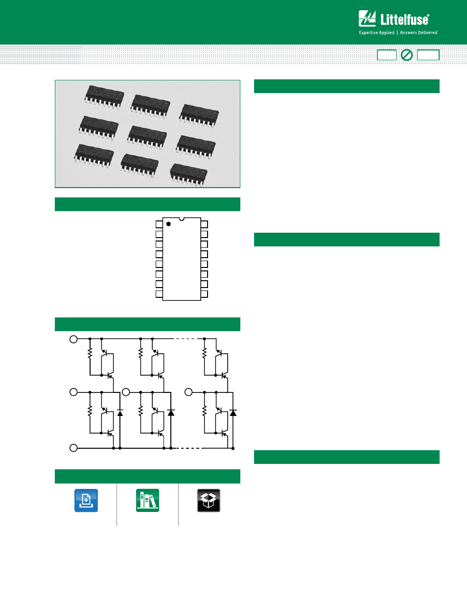
Applications
The SP720 is an array of SCR/Diode bipolar structures for
ESD and over-voltage protection to sensitive input circuits.
The SP720 has 2 protection SCR/Diode device structures
per input. A total of 14 available inputs can be used to
protect up to 14 external signal or bus lines. Over-voltage
protection is from the IN (pins 1-7 and 9-15) to V+ or V-.
The SCR structures are designed for fast triggering at a
threshold of one +V
BE
diode threshold above V+ (Pin 16) or
a -V
BE
diode threshold below V- (Pin 8). From an IN input,
a clamp to V+ is activated if a transient pulse causes the
input to be increased to a voltage level greater than one
V
BE
above V+. A similar clamp to V- is activated if a negative
pulse, one V
BE
less than V-, is applied to an IN input.
Standard ESD Human Body Model (HBM) Capability is:
• Microprocessor/Logic
Input Protection
• Data Bus Protection
• Analog Device Input
Protection
• Voltage Clamp
Pinout
Functional Block Diagram
V+ 16
1
8
2
3 - 7
9 - 15
IN
IN
IN
V-
RoHS
Pb
GREEN
SP720 (PDIP, SOIC)
TOP VIEW
14
15
16
9
13
12
11
10
1
2
3
4
5
7
6
8
IN
IN
IN
IN
IN
IN
V-
IN
V+
IN
IN
IN
IN
IN
IN
IN
Life Support Note:
Not Intended for Use in Life Support or Life Saving Applications
The products shown herein are not designed for use in life sustaining or life saving
applications unless otherwise expressly indicated.
SP720 Series 3pF 4kV Diode Array
Additional Information