Littelfuse E1 Sensitive Triacs User Manual
Page 7
Data Sheets
Sensitive Triacs
©2004 Littelfuse, Inc.
E1 - 7
http://www.littelfuse.com
Thyristor Product Catalog
+1 972-580-7777
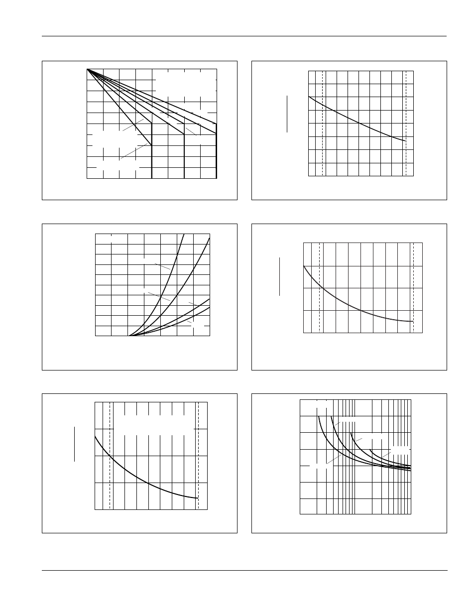
Figure E1.3 Maximum Allowable Case Temperature versus
On-state Current (4 A, 6 A, and 8 A)
Figure E1.4 On-state Current versus On-state Voltage (Typical)
Figure E1.5 Normalized DC Holding Current versus Case Temperature
Figure E1.6 Normalized DC Gate Trigger Voltage for All Quadrants
versus Case Temperature
Figure E1.7 Normalized DC Gate Trigger Current for All Quadrants
versus Case Temperature
Figure E1.8 Turn-on Time versus Gate Trigger Current (Typical)
0
1
2
3
4
5
6
7
8
60
65
70
75
80
85
90
95
100
105
110
RMS On-State Current [I
T(RMS)
] - Amps
Maximum Allowable Case Temperature
( T
C
) - ˚C
CURRENT WAVEFORM: Sinusoidal
LOAD: Resistive or Inductive
CONDUCTION ANGLE: 360˚
CASE TEMPERATURE: Measured as
shown on Dimensional Drawings
4 A TYPE 1 and 3 TO-202
4 A TO-220 (Isolated)
4 A TO-252
8 A TO-220 (Isolated)
6 A TO-220 (Isolated)
4 A TYPE 2 and 4 TO-202
4 A TO-251
8 A TO-251 and TO-252
6 A TO-251
6 A TO-252
0
0.5
0.8
1.0
1.2
1.4
1.6
1.8
0
2
4
6
8
10
12
14
16
18
20
Positive or Negative Instantaneous
On-state Voltage (v
T
) - Volts
Positive or Negative Instantaneous
On-state Current (i
T
) - Amps
1 A
4 A
6 A and 8 A
T
C
= 25
˚
C
0.8 A
-40
-15
+25
+65
+110 +125
0
1.0
2.0
3.0
4.0
-65
Case Temperature (T
C
) -
˚
C
INITIAL ON-STATE CURRENT
= 100 mA (DC) 0.8 - 4 A Devices
= 200 mA (DC) 6 - 8 A Devices
Ratio of
I
H
I
H
(T
C
= 25
˚
C)
-65
-40
-15
+65
+110 +125
+25
0
.5
1.0
1.5
2.0
Ratio of
V
GT
V
GT
(T
C
= 25 ˚C)
Case Temperature (T
C
) - ˚ C
-65
-40
-15
+65
+110 +125
+25
0
1.0
2.0
3.0
4.0
Ratio of
I
GT
I
GT
(T
C
= 25 ˚C)
Case Temperature (T
C
) - ˚C
1
2
3
4
6
5
8
10
20
30
40
60
80 100
I
GT
= 5 mA MAX
I
GT
= 10 mA MAX
I
GT
= 20 mA
MAX
I
GT
= 3 mA MAX
0
1.0
2.0
3.0
4.0
5.0
6.0
7.0
DC Gate Trigger Current (I
GT
) - mA
Turn-On Time (t
gt
) -
µ
Sec
T
C
= 25 ˚C