Gate characteristics – Littelfuse E1 Sensitive Triacs User Manual
Page 5
Data Sheets
Sensitive Triacs
©2004 Littelfuse, Inc.
E1 - 5
http://www.littelfuse.com
Thyristor Product Catalog
+1 972-580-7777
Electrical Specification Notes
(1) For either polarity of MT2 with reference to MT1 terminal
(2) For either polarity of gate voltage V
GT
with reference to MT1
terminal
(3) See Gate Characteristics and Definition of Quadrants.
(4) See Figure E1.4 for i
T
versus v
T
.
(5) See Figure E1.6 for V
GT
versus T
C
.
(6) See Figure E1.7 for I
GT
versus T
C
.
(7) See Figure E1.5 for I
H
versus T
C
.
(8) See Figure E1.9 for surge rating and specific duration.
(9) See Figure E1.8 for t
gt
versus I
GT
.
(10) See Figure E1.2 and Figure E1.3 for maximum allowable case
temperature at maximum rated current.
(11) See Figure E1.1, Figure E1.2, and Figure E1.3 for T
A
or T
C
versus
I
T(RMS)
.
(12) See package outlines for lead form configurations. When ordering
special lead forming, add type number as suffix to part number.
(13) Pulse width
≤10 µs
(14) T
C
or T
L
= T
J
for test conditions in off state
(15) Minimum non-trigger V
GT
at 110 °C is 0.2 V.
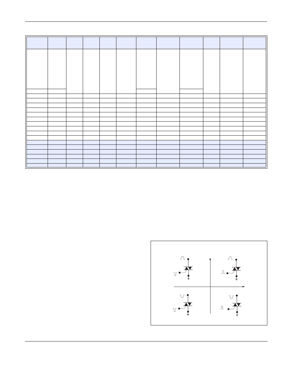
Gate Characteristics
Teccor triacs may be turned on between gate and MT1 terminals
in the following ways:
•
In-phase signals (with standard AC line) using Quadrants I
and III
•
Application of unipolar pulses (gate always positive or nega-
tive), using Quadrants II and III with negative gate pulses and
Quadrants I and IV with positive gate pulses
When maximum surge capability is required, pulses should be a
minimum of one magnitude above I
GT
rating with a steep rising
waveform (
≤
1 µs rise time).
Definition of Quadrants
V
TM
V
GT
I
H
I
GTM
P
GM
P
G(AV)
I
TSM
dv/dt(c)
dv/dt
t
gt
I
2
t
di/dt
(1) (4)
Volts
(2) (5) (15)
Volts
(1) (7)
mAmps
(13)
Amps
(13)
Watts
Watts
(8) (10)
Amps
(1) (10)
Volts/µSec
(1)
Volts/µSec
(9)
µSec
Amps
2
Sec
Amps/µSec
T
C
= 25 °C
T
C
= 25 °C
60/50 Hz
T
C
= 100 °C
MAX
MAX
MAX
TYP
TYP
TYP
1.6
2
10
1.6
18
0.4
60/50
1
40
3
15
70
1.6
2
10
1.6
18
0.4
60/50
1
30
3
15
70
1.6
2
10
1.6
18
0.4
60/50
1
20
3
15
70
1.6
2
10
1.6
18
0.4
60/50
2
40
3
15
70
1.6
2
10
1.6
18
0.4
60/50
2
30
3
15
70
1.6
2
10
1.6
18
0.4
60/50
2
20
3
15
70
1.6
2
20
1.6
18
0.4
60/50
2
45
3.2
15
70
1.6
2
20
1.6
18
0.4
60/50
2
40
3.2
15
70
1.6
2
20
1.6
18
0.4
60/50
2
30
3.2
15
70
1.6
2
10
1.6
18
0.4
80/65
2
40
3
26.5
70
1.6
2
10
1.6
18
0.4
80/65
2
30
3
26.5
70
1.6
2
10
1.6
18
0.4
80/65
2
20
3
26.5
70
1.6
2
20
1.6
18
0.4
80/65
2
45
3.2
26.5
70
1.6
2
20
1.6
18
0.4
80/65
2
40
3.2
26.5
70
1.6
2
20
1.6
18
0.4
80/65
2
30
3.2
26.5
70
MT2 POSITIVE
(Positive Half Cycle)
MT2 NEGATIVE
(Negative Half Cycle)
MT1
MT2
+
I
G T
REF
QII
MT1
I
G T
GATE
MT2
REF
MT1
MT2
REF
MT1
MT2
REF
QI
QIV
QIII
ALL POLARITIES ARE REFERENCED TO MT1
(
-
)
I
G T
GATE
(+)
I
G T
-
I
G T
GATE
(
-
)
I
G T
GATE
(+)
+
-