Teccor, Brand thyristors, 1 amp sensitive & standard triacs – Littelfuse QxNx Series User Manual
Page 4
38
Revised: 09/23/13
©2013 Littelfuse, Inc
Specifications are subject to change without notice.
Teccor
®
brand Thyristors
1 Amp Sensitive & Standard Triacs
Lx01Ex & LxNx & Qx01Ex & QxNx Series
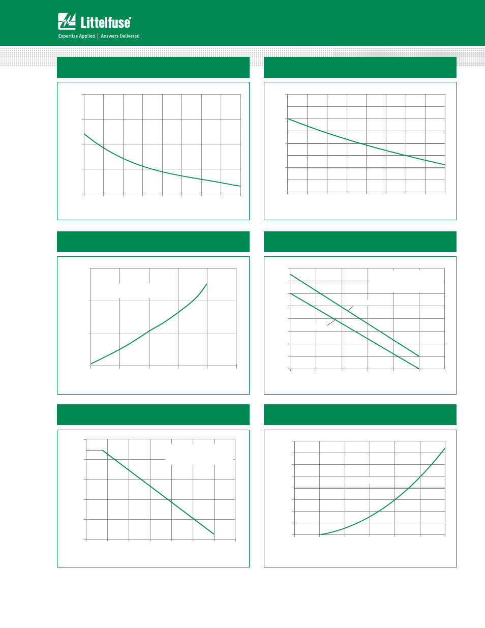
Figure 3: Normalized DC Holding Current
vs. Junction Temperature
0.0
1.0
2.0
3.0
4.0
-65
-40
-15
10
35
60
85
110
125
Junction Temperature (Tj) - ºC
Ratio of
I
H
/ I
H
(T
j
= 2
5
ºC)
Figure 4: Normalized DC Gate Trigger Voltage for
All Quadrants vs. Junction Temperature
0.0
0.5
1.0
1.5
2.0
-65 -40 -15 10 35 60 85 110 125
Junction Temperature (T
j
) - ºC
Ratio of
V
GT
/V
GT
(T
j
= 2
5
ºC)
RMS On-State Current (I
T(RMS)
) - Amps
1.25
1.0
0.5
0.75
0.25
0
0.0
Average On-State
Power Dissipation (P
D(AV)
) - Watts
0.5
1.5
CURRENT WAVE FORM: Sinusoidal
LOAD: Resistive or Inductive
CONDUCTION ANGLE: 360°
1.0
Figure 5: Power Dissipation (Typical)
vs. RMS On-State Current
Figure 6: Maximum Allowable Case Temperature
vs. On-State Current
50
60
70
80
90
100
110
120
130
0 0.2 0.4 0.6 0.8 1 1.2
RMS On-State Current [I
T(RMS)
] - AMPS
Max Allowable Case Tem
p
er
atu
re
(T
C
) - ºC
CURRENT WAVE FORM: Sinusoidal
LOAD: Resistive or Inductive
CONDUCTION ANGLE: 360º
CASE TEMPERATURE: Measured as shown
on Dimensional Drawing
Lx01Ex / LxNx
Qx01Ex /QxNx
Figure 8: On-State Current vs. On-State Voltage
(Typical)
T
C
= 25ºC
0
1
2
3
4
5
6
7
8
0.6 0.8 1.0 1.2 1.4 1.6 1.8
Positive or Negative Instantaneous On-State Voltage
(V
T
) - Volts
P
o
sitive or
Negative Instantaneous
On-State Current (I
T
) - AMPS
Figure 7: Maximum Allowable Ambient Temperature
vs. On-State Current
20
40
60
80
100
120
0.0 0.1 0.2 0.3 0.4 0.5 0.6 0.7
RMS On-State Current [I
T(RMS)
] - AMPS
Max Allowable Am
bient Te
m
p
er
atur
e
(T
A
) - ºC
CURRENT WAVEFORM: Sinusoidal
LOAD: Resistive or Inductive
CONDUCTION ANGLE: 360º
FREE AIR RATING - NO HEATSINK