Teccor, Brand thyristors, Soldering parameters – Littelfuse Qxx16xHx Series User Manual
Page 5
125
Revised: 09/23/13
©2013 Littelfuse, Inc
Specifications are subject to change without notice.
Teccor
®
brand Thyristors
15 Amp Standard & 16 Amp Alternistor (High Commutation) Triacs
Qxx15xx & Qxx16xHx Series
10
100
1000
1000
100
10
1
Surge Current Duration - Full Cycles
Peak Surge (Non-Repetitive) On-State
Current (I
TSM
) - AMPS
Figure 10: Surge Peak On-State Current vs. Number of Cycles
Supply Frequency: 60Hz Sinusoidal
Load: Resistive
RMS On-State [I
T(RMS)
]: Max Rated Value at
Specific Case Temperature
Notes:
1. Gate control may be lost during and immediately
following surge current interval.
2. Overload may not be repeated until junction
temperature has returned to steady-state
rated value.
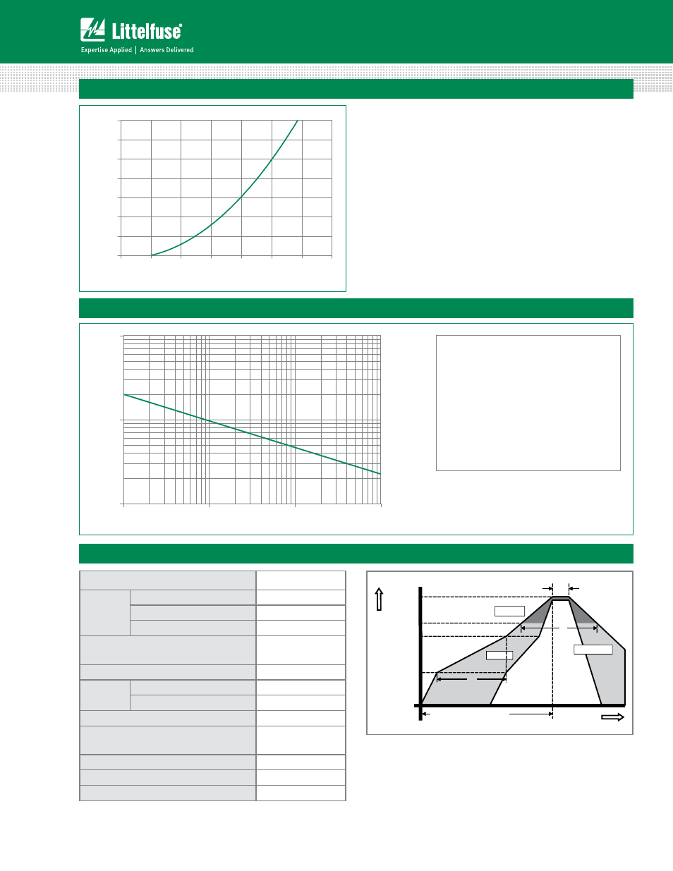
Soldering Parameters
Reflow Condition
1Co'SFFBTTFNCMZ
Pre Heat
- Temperature Min (T
s(min)
)
150°C
- Temperature Max (T
s(max)
)
200°C
- Time (min to max) (t
s
)
oTFDT
Average ramp up rate (Liquidus Temp)
(T
L
) to peak
5°C/second max
T
S(max)
to T
L
- Ramp-up Rate
5°C/second max
Reflow
- Temperature (T
L
) (Liquidus)
217°C
- Temperature (t
L
)
oTFDPOET
Peak Temperature (T
P
)
260
+0/5
°C
Time within 5°C of actual peak
Temperature (t
p
)
oTFDPOET
Ramp-down Rate
5°C/second max
Time 25°C to peak Temperature (T
P
)
8 minutes Max.
Do not exceed
280°C
Figure 9: On-State Current vs. On-State Voltage (Typical)
T
J
= 25ºC
0
10
20
30
40
50
60
70
0.6 0.8 1.0 1.2 1.4 1.6 1.8 2.0
Positive or Negative Instantaneous On-State Voltage (v
T
) - Volts
P
o
sitive or
Negative Instantaneous
On-S
tate Cu
rr
e
nt(i
T
) - AMPS
Time
T
emperature
T
P
T
L
T
S(max)
T
S(min)
25
t
P
t
L
t
S
time to peak temperature
Preheat
Preheat
Ramp-up
Ramp-up
Ramp-down
Ramp-do