Pulseguard, Suppressors, Surface mount polymeric esd suppressors – Littelfuse PGB20402 Series User Manual
Page 5
www.littelfuse.com
©2011 Littelfuse
PGB2 Series
Specifications are subject to change without notice.
5
Revised: March 8, 2011
PulseGuard
®
Suppressors
Surface Mount Polymeric ESD Suppressors
Two of the most common methods used in industry for
characterizing the performance of ESD suppressors are
ESD transient testing, per IEC 61000-4-2 ESD waveform,
BOE5-14JODFOPTUBOEBSETFYJTUGPSNFBTVSFNFOUBOE
qualification of ESD suppressor performance, these
two methods have become the de-facto standard for
determining device trigger and clamp specifications. It
is common to see trigger values to be based on the TLP
method and clamping values based on the ESD transient
method. Low voltage TLP obtained trigger values most
closely resemble device DC turn-on .Since the two test
NFUIPETBSFEJGGFSFOUBOEOPNFUIPEFYJTUTUPBDDVSBUFMZ
correlate suppressor response between the two test
methods, trigger and clamp values should be specified for
each method.
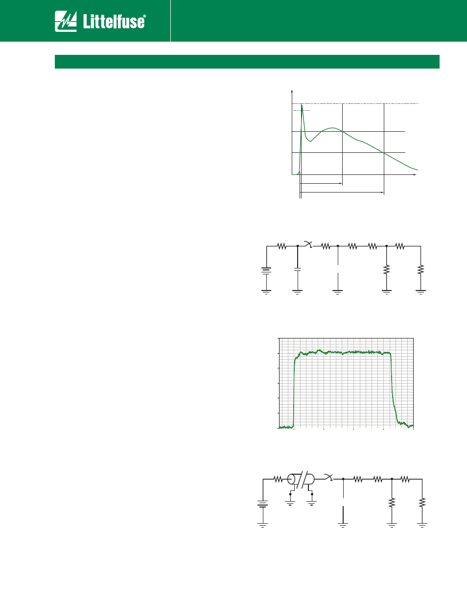
ESD transient testing, which is based on the IEC 61000-4-2
standard waveform, consists of subjecting a ESD
suppressor to an subnanosecond risetime 8Kv transient
generated by a commercial ESD simulator and recording
trigger and clamp voltage levels. Clamp voltage level is
obtained at 25ns. The basic ESD simulator circuit consists
PGB3$EJTDIBSHFOFUXPSLXJUI3BOE$WBMVFTPG
PINTBOEQJDPGBSBET8BWFGPSNTBSFDBQUVSFEVTJOHB
4 GHz oscilloscope(50 ohm input) with 20X resistive divider
probes and a 30dB attenuator. Figures 1 and 2 show IEC
current waveform and test setup.
5SBOTNJTTJPOMJOF1VMTFUFTUJOH
DPNNPOMZLOPXBT
TLP testing consists of subjecting a ESD suppressor
to a 50 ohm transmission line discharge pulse with a
subnanosecond risetime and a pulse width of 65ns. Trigger
values are obtained by varying the TLP voltage until a
EFWJDFUSJHHFSWPMUBHFJTEFUFSNJOFE0ODFUIFEFWJDFJT
USJHHFSFE
BDMBNQWBMVFJTEFUFSNJOFEBUOT8BWFGPSNT
are captured using a 4 GHz oscilloscope(50 ohm input)
with 20X resistive divider probes and a 30dB attenuator.
Figures 3 and 4 show a typical TLP voltage waveform and
test setup.
*UTIPVMECFOPUFEUIBUOPNFBTVSFNFOUTUBOEBSEFYJUT
for obtaining trigger and clamp voltage levels. Trigger and
clamp values will vary from one test setup to another.
Due to the subnanosecond risetime of ESD and TLP
waveforms, any parasitic inductance and capacitance in
UIFUFTUTZTUFNXJMMBGGFDUNFBTVSFNFOUT"OZFGGFDUT
due to inductance and capacitance need to be subtracted
from the final measurement. It is important to remember
that the test system will introduce a load across the
ESD suppressor under test and this will also affect
NFBTVSFNFOUT"IJHICBOEXJEUI0INPTDJMMPTDPQF
and probes(>1Ghz) need to be used for obtaining best
SFTVMUT"UUFOVBUJPOWBMVFTGPSUIFQSPCFUJQTIPVMECF
at least 20X in order to obtain high input impedance for
measurements.
Characterization Methods for ESD Suppressors
Time in nanoseconds
0
20
40
60
80
V
olts
0
100
200
300
400
500
600
100%
90%
I
I
10%
30n
60n
tr = 0.7 to 1.0ns
Cur
rent (I) %
30
60
50
3.165
150pf
8000
DUT
1
2
330
950
46.93
46.93
+
-
ESD Simulator
Scope Probe
30db Attenuator
50 Ohm
Scope Input
50 Ohm
Scope Input
50
3.165
500
DUT
1
2
950
46.93
46.93
+
-
TLP
Scope Probe
30db Attenuator
Figure 3
Figure 4
Figure 1
Figure 2