Pulseguard, Suppressors, Surface mount polymeric esd suppressors – Littelfuse PGB20402 Series User Manual
Page 3
www.littelfuse.com
©2011 Littelfuse
PGB2 Series
Specifications are subject to change without notice.
3
Revised: March 8, 2011
PulseGuard
®
Suppressors
Surface Mount Polymeric ESD Suppressors
Environmental Specifications
Operating Temperature
-65°C to +125°C
Biased Humity:
Biased Heat:
40°C, 95% RH, 1000 hours
85°C, 1000 hours
Thermal Shock
MIL-STD-202, Method 107G,
-65°C to 125°C, 30 min. cycle,
10 cycles
Vibration
.*-45% .FUIPE"
Chemical Resistance
MIL-STD-202, Method 215
Solder Leach Resistance and
Terminal Adhesion
*1$&*"+45%
Physical Specifications
Materials
#PEZ&QPYZ(MBTT4VCTUSBUF
5FSNJOBUJPOT$V/J4O
Device Weight
0.349 mg
Solderability
MIL-STD-202, Method 208
Soldering
Parameters
8BWFTPMEFS¡$
TFDPOETNBYJNVN
3FnPXTPMEFS¡$
TFDPOETNBYJNVN
Design Consideration
Because of the fast rise-time of the ESD transient, proper
QMBDFNFOUPG1VMTF(VBSETVQQSFTTPSTBSFBLFZEFTJHO
consideration to achieving optimal ESD suppression. The
devices should be placed on the circuit board as close to the
source of the ESD transient as possible. Install PulseGuard
TVQQSFTTPST DPOOFDUFEGSPNTJHOBMEBUBMJOFUPHSPVOE
directly behind the connector so that they are the first board-
level circuit component encountered by the ESD transient.
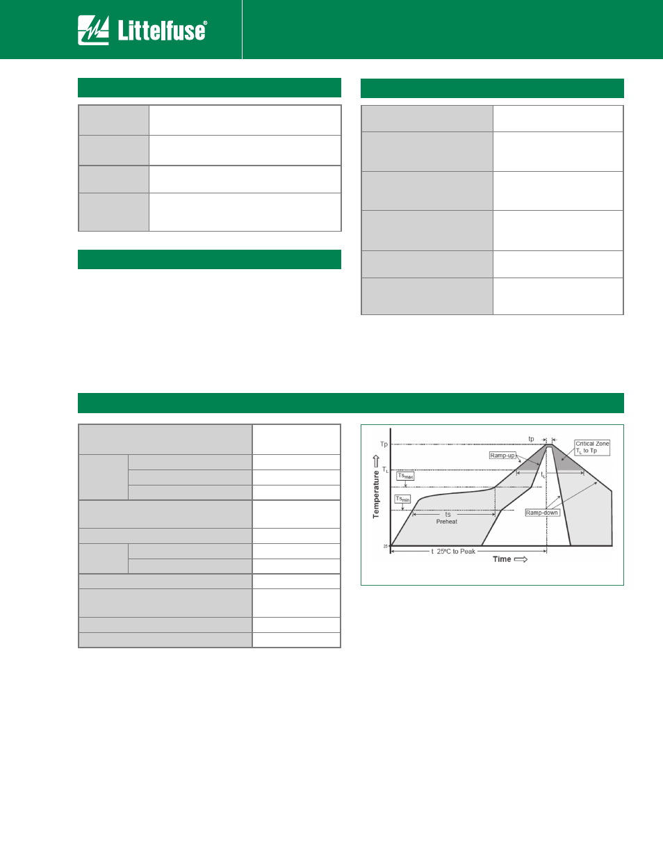
Soldering Parameters
Reflow Condition
Pb – Free assembly
Pre Heat
- Temperature Min (T
s(min)
)
150°C
- Temperature Max (T
s(max)
)
200°C
- Time (min to max) (t
s
)
60 – 180 seconds
Average ramp up rate (Liquidus Temp
(T
L
) to peak
¡$TFDPOENBY
T
S(max)
to T
L
- Ramp-up Rate
¡$TFDPOENBY
Reflow
- Temperature (T
L
) (Liquidus)
217°C
- Temperature (t
L
)
60 – 150 seconds
Peak Temperature (T
P
)
260°C
Time within 5°C of actual peak
Temperature (t
p
)
10 – 30 seconds
Ramp-down Rate
¡$TFDPOENBY
Time 25°C to peak Temperature (T
P
)
NJOVUFTNBY
Notes:
- PGB2 Series recommended for reflow soldering only
3FDPNNFOEFEQSPmMFCBTFEPO*1$+&%&%+45%$
- For recommended soldering pad layout dimensions,
please refer to Dimensions section of this data sheet