Varistor products – Littelfuse MHS Varistor Series User Manual
Page 5
© 2013 Littelfuse, Inc.
27
Revised: December 16, 2013
Varistor Products
MHS S
eries
MHS Varistor Series
Surface Mount Multilayer Varistors (MLVs) > MHS Series
Specifications are subject to change without notice.
Please refer to www.littelfuse.com/series/MHS.html for current information.
Part Numbering System
V 0402
PACKING OPTIONS
(See quantities in Packaging section)
DEVICE FAMILY
Littelfuse TVSS Device
R
DEVICE SIZE
0402 = .04 inch x .02 inch
(1.0 mm x 0.5 mm)
0603 = .063 inch x .031 inch
(1.6 mm x 0.8 mm)
MHS 03 N
CAPACITANCE DESIGNATION
03 = 3pF
12 = 12pF
22 = 22pF
END TERMINATION OPTION
N = Nickel Barrier (Ni/Sn)
SERIES DESIGNATOR
MHS = Multilayer Hi-Speed
T = (0603 device only)13in (330mm) Diameter Reel, Plastic Carrier Tape
H = (0603 device only) 7in (178mm) Diameter Reel, Plastic Carrier Tape
R = (available for 0402 and 0603 devices) 7in (178mm) Diameter Reel, Paper Carrier Tape
Packaging*
Quantity
Device Size
13 Inch Reel
("T" Option)
7 Inch Reel
("H" Option)
7 Inch Reel
("R" Option)
0603
10,000
2,500
4,000
0402
not available
not available
10,000
K
0
T
1
D
0
P
0
D
1
P
1
A
0
P
2
B
0
F
E
W
T
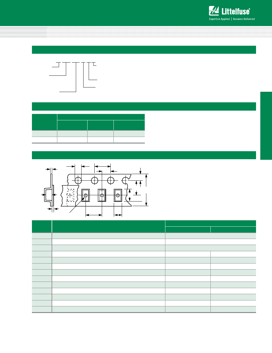
Tape and Reel Specifications
Symbol
Description
Dimensions in Millimeters
0402 Size
0603 Size
A
0
Width of Cavity
Dependent on Chip Size to Minimize Rotation.
B
0
Length of Cavity
Dependent on Chip Size to Minimize Rotation.
K
0
Depth of Cavity
Dependent on Chip Size to Minimize Rotation.
W
Width of Tape
8 -/+ 0.2
8 -/+ 0.3
F
Distance Between Drive Hole Centers and Cavity Centers
3.5 -/+.05
3.5 -/+.05
E
Distance Between Drive Hole Centers and Tape Edge
1.75 -/+ 0.1
1.75 -/+ 0.1
P
1
Distance Between Cavity Centers
2 -/+ 0.05
4 -/+ 0.1
P
2
Axial Drive Distance Between Drive Hole Centers & Cavity Centers
2 -/+ 0.1
2 -/+ 0.1
P
0
Axial Drive Distance Between Drive Hole Centers
4 -/+ 0.1
4 -/+ 0.1
D
0
Drive Hole Diameter
1.55 -/+ 0.05
1.55 -/+ 0.05
D
1
Diameter of Cavity Piercing
N/A
1.05 -/+ 0.05
T
1
Top Tape Thickness
0.1 Max
0.1 Max
T
Nominal Carrier Tape Thickness
1.1
1.1
Notes:
• Conforms to EIA-481-1, Revision A
• Can be supplied to IEC publication 286-3
*(Packaging) It is recommended that parts be kept in the sealed bag provided and that parts be used as soon as possible when removed from bags.