Varistor products, Repetitive load dump pulsing at rated energy, And maximum (v – Littelfuse AUML Varistor Series User Manual
Page 4: Voltage specified
© 2013 Littelfuse, Inc.
58
Revised: May 8, 2013
Varistor Products
AUML Varistor Series
Surface Mount Multilayer Varistors (MLVs) > AUML Series
Specifications are subject to change without notice.
Please refer to www.littelfuse.com/series/AUML.html for current information.
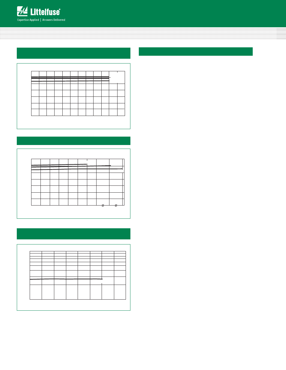
AUML Load Dump Pulsing over a Temperature Range of
-55ºC to +125ºC
Repetitive Energy Testing of V18AUMLA2220
at an Energy Level of 2 Joules
V(10mA)
35
30
25
20
15
10
5
0
0
1
2
3
4
5
6
7
8
9
10
11
12
V
O
LTA
G
E
# OF LOAD DUMPS
2220 = 25J
1812 = 6J
1210 = 3J
# OF LOAD DUMPS
V(10mA)
35
30
25
20
15
10
5
0
0
50
100
150
200
250
300
350
1,000
2,000
V
O
LTA
G
E
2220 = 25J
1812 = 6J
1210 = 3J
V AT 10mA
100
10
1000
2000
3000
4000
5000
6000
7000
V18AUMLA2220
V
O
LTA
G
E
NUMBER OF PULSES
Repetitive Load Dump Pulsing at Rated Energy
Figure 6
Figure 7
Figure 8
Explanation of Terms
Maximum Continuous DC Working Voltage (*V
M*(DC)++
)
This is the maximum continuous DC voltage which may
be applied, up to the maximum operating temperature
(125ºC), to the ML suppressor. This voltage is used as the
reference test point for leakage current and is always less
than the breakdown voltage of the device.
Load Dump Energy Rating *W
LD+
This is the actual energy the part is rated to dissipate
under Load Dump conditions (not to be confused with the
"source energy" of a Load Dump test specification).
Maximum Clamping Voltage *V
C+
This is the peak voltage appearing across the suppressor
when measured at conditions of specified pulse current
and specified waveform (8/20μs). It is important to note
that the peak current and peak voltage may not necessarily
be coincidental in time.
Leakage Current *I
L+
In the nonconducting mode, the device is at a very
high impedance (approaching 10
6
Ω at its rated working
voltage) and appears as an almost open circuit in the
system. The leakage current drawn at this level is very
low (<25μA at ambient temperature) and, unlike the
Zener diode, the multilayer TVS has the added advantage
that, when operated up to its maximum temperature,
its leakage current will not increase above 500μA.
Nominal Voltage *V
N*DC++
This is the voltage at which the AUML enters its
conduction state and begins to suppress transients.
In the automotive environment this voltage is
defined at the 10mA point and has a minimum
(V
N(DC) MIN
) and maximum (V
N(DC) MAX
) voltage specified.