Varistor products, Device ratings and specifications – Littelfuse AUML Varistor Series User Manual
Page 2
© 2013 Littelfuse, Inc.
56
Revised: May 8, 2013
Varistor Products
AUML Varistor Series
Surface Mount Multilayer Varistors (MLVs) > AUML Series
Specifications are subject to change without notice.
Please refer to www.littelfuse.com/series/AUML.html for current information.
Device Ratings and Specifications
Part Number
Maximum Ratings (125
ºC
)
Specifications (25
ºC
)
Maximum
Continuous
DC Voltage
Jump Start
Voltage
(5 Min)
Load Dump
Energy
(10 Pulses)
Nominal Varistor Voltage
at 10mA
DC Test Current
Maximum
Standby Leakage
(at 13V DC)
Maximum Clamping
Voltage (V
C
) at
Test Current (8/20μs)
V
M(DC)
V
JUMP
W
LD
V
N(DC)
Min
V
N(DC)
Max
I
L
V
C
I
P
(V)
(V)
(J)
(V)
(V)
(μA)
(V)
(A)
V18AUMLA1206
18
24.5
1.5
23
32
50
40
1.5
V18AUMLA1210
18
24.5
3.0
23
32
50
40
1.5
V18AUMLA1812
18
24.5
6.0
23
32
100
40
5.0
V18AUMLA2220
18
24.5
25
23
32
200
40
10.0
NOTES: 1. Average power dissipation of transients not to exceed 0.1W, 0.15W, 0.3W and 1W for model sizes 1206, 1210, 1812 and 2220 respectively.
2. Load Dump energy rating (into the suppressor) of a voltage transient with a resultant time constant of 115ms to 230ms.
3. Thermal shock capability per Mil-Std-750, Method 1051: -55ºC to 125ºC, 5 minutes at 25ºC, 25 Cycles: 15 minutes at each extreme.
4. For application specific requirements, please contact Littelfuse.
For automotive 24V and 42V applications please contact your Littelfuse representative or visit www.littelfuse.com for the latest product update.
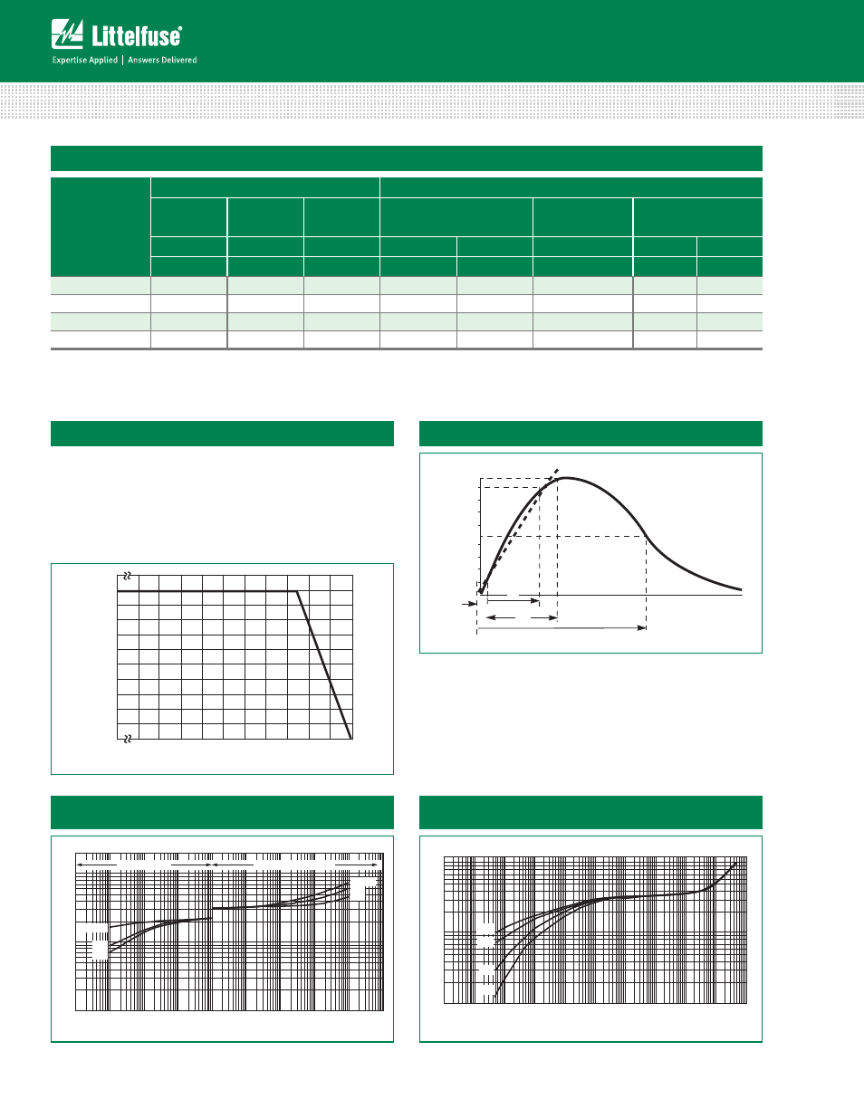
Current, Energy and Power Derating Curve
When transients occur in rapid succession, the average
power dissipation is the energy (watt-seconds) per pulse
times the number of pulses per second. The power so
developed must be within the specifications shown on the
Device Ratings and Characteristics Table for the specific
device. Certain parameter ratings must be derated at high
temperatures as shown below.
100
90
80
70
60
50
40
30
20
10
0
-55
50
60
70
80
90
100
110
120
130
140
150
PERCENT OF R
A
TED
V
ALUE
AMBIENT TEMPERATURE (oC)
T
1
T
2
100
50
0
O
1
TIME
PERCENT OF PEAK
V
ALUE
T
Peak Pulse Current Test Waveform for Clamping Voltage
Typical V-I Characteristics of the V18AUMLA2220 at -40ºC,
25ºC, 85ºC and 125ºC
Maximum Leakage Current/Clamping Voltage Curve for
AUML Series at 25ºC
V
O
LTA
G
E
100
1
1mA
10mA
100mA
1A
10A
100A
CURRENT
100μA
10μA
10
1210/1206
1812
2220
MAXIMUM LEAKAGE
MAXIMUM CLAMPING VOLTAGE
1210/1206
1812
2220
100
10
1
1μA
10μA
100μA
1mA
-40
o
C
25
o
C
85
o
C
10mA
100mA
1A
10A
100A
1000A
CURRENT
125
o
C
V
O
LTA
G
E
0
1
= Virtual Origin of Wave
T = Time from 10% to 90% of Peak
T
1
= Rise Time = 1.25 x T
T
2
= Decay Time
Example - For an 8/20 μs Current Waveform:
8μs = T
1
= Rise Time
20μs = T
2
= Decay Time
Figure 1
Figure 2
Figure 3
Figure 4