Teccor, Brand thyristors, Ev series 0.8 amp sensitive scrs – Littelfuse SxX8xSx Series User Manual
Page 3
201
Revised: 09/23/13
©2013 Littelfuse, Inc
Specifications are subject to change without notice.
Teccor
®
brand Thyristors
EV Series 0.8 Amp Sensitive SCRs
SxX8xSx Series
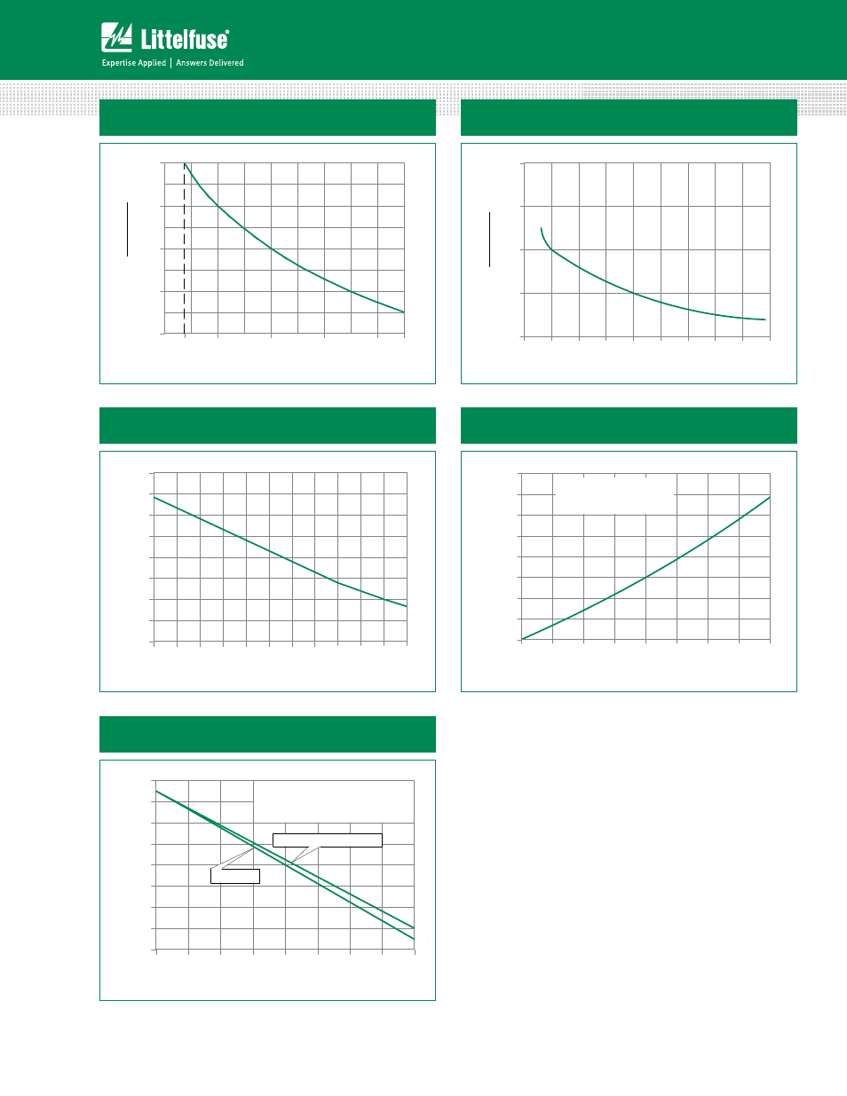
Figure 3: Normalized DC Gate Trigger Voltage
vs. Junction Temperature
-40
-25
-10
+5
+20
+35
+50
+65
+80
+95
+110
+125
0.2
0.3
0.4
0.5
0.6
0.7
0.8
0.9
1.0
Junction Temperature (T
J
) - °C
Gate Trigger Voltage (V
GT
) - V
Figure 1: Normalized DC Gate Trigger Current For All
Quadrants vs. Junction Temperature
-40
-15
+25
+65
+105
0.0
0.5
1.0
1.5
2.0
Junction Temperature (T
J
) - °C
Ratio of
+125
I
GT
I
GT
(T
J
= 2
5
°C)
Figure 4: Power Dissipation (Typical)
vs. RMS On-State Current
Figure 2: Normalized DC Holding Current
vs. Junction Temperature
-55
-35
-15
+5
+25
+45
+65
+85
+105
0.0
1.0
2.0
3.0
4.0
Junction Temperature (T
J
) - °C
+125
I
H
(T
J
= 2
5
°C)
I
H
Ratio of
Figure 5: Maximum Allowable Case Temperature
vs. On-State Current
0.0
0.1
0.2
0.3
0.4
0.5
0.6
0.7
0.8
50
60
70
80
90
100
110
120
130
RMS On-state Current [I
T(RMS)
] - Amps
Maximum Allo
w
able
Case
Temper
at
ur
e
(T
C
) -
o
C
TO-92
SOT-223 & SOT-89
CURRENT WAVEFORM: Sinusoidal
LOAD: Resistive or Inductive
CONDUCTION ANGLE: 180
o
CASE TEMPERATURE: Measured as
shown on dimensional drawings
0.0
0.1
0.2
0.3
0.4
0.5
0.6
0.7
0.8
0.0
0.1
0.2
0.3
0.4
0.5
0.6
0.7
0.8
RMS On-state Current [I
T(RMS)
] - Amps
A
v
er
ag
e On-stat
e P
o
w
er Dissipation
[P
D(A
V)
] -
W
a
tt
s
CURRENT WAVEFORM: Sinusoidal
LOAD: Resistive or Inductive
CONDUCTION ANGLE: 180
o