StreetGlow 5 Position Switch Panel User Manual
Front back 5in 6in
Installation Instructions
5 POSITION SWITCH PANEL
5 POSITION SWITCH PANEL
SGSW5
Installation Instructions
CONTENTS
1 - SGSW5 switch panel
All necessary mounting hardware and
Installation instructions
2 Year Limited Warranty
StreetGlow products are warranted against defects in the
material and /or workmanship according to the following
conditions and limitations:
1. Broken Glass, Labor and transportation are not covered
regardless.
2. Warranty is valid for 2 years from date of purchase.
3. Proof of purchase is required to validate warranty.
4. All warranty claims are to be handled by selling agents.
5. Accident, abuse, neglect, improper installation, not
used for its intended purpose are not covered. This
warranty is limited to replacing the defective part
without charge. The company in no event shall be held
responsible for any consequential or special damages.
This warranty gives you specific legal rights and you
may also have rights which vary from state to state.
WARNING!
The retailer shall not be held responsible for any damages
that occur as a result of defective products. StreetGlow
products are recommended for show and off-road use
only. Laws concerning the use of aftermarket lighting
products may vary from state to state. For more
information, check with your local authority.
5 POSITION SWITCH PANEL
SGSW5
Installation Instructions:
1) Choose a location to mount SGSW5 switch panel.
2) The mounting surface must be clean and free of
all dirt, wax and oil prior to the installation. Wipe
all areas with the alcohol prep pad provided and
let dry thoroughly.
3) Mount switch panel to the desired location with
two (2) mounting screws (provided) or with
double faced tape provided in our mounting
hardware kit.
4) Switch panel is powered by direct connection to
a 12v power source.
Striped wire = (+) 12v
Solid wire = (-) ground
Connecting a 12v lighting device to the back of the
switch panel. (see figure 2)
1) Up to four (4) lighting devices may be controlled
by the SGSWS5 switch panel.
2) Select the red push clip that corresponds to the
desired numbered switch (1 through 4). Connect
the striped wire (+) 12v to the red push clip.
3) Select the corresponding black push clip and
connect the solid color wire (-) ground to the black
push clip.
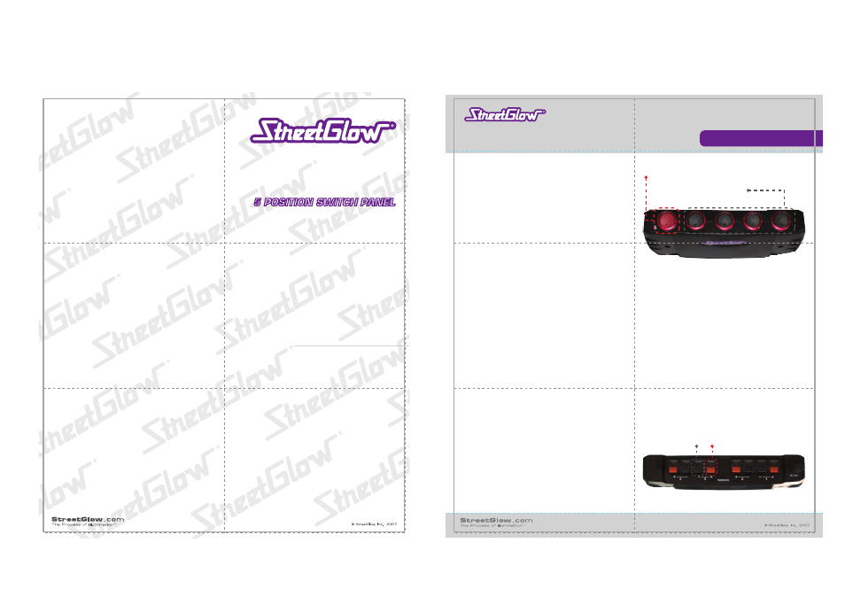
1
RED
main power switch
4
BLACK sub-switches
The main power switch controls all sub-switches
(see figure 1). With the main power on, the
sub-switches may be used to individually control
up to four (4) lighting devices.
There are a total of 12 amps available for the four
black sub-switches with a maximum of 3 amps per
black sub-switch. Each sub-switch contains a built
in resettable fuse on each output which will trip in
the event of overload. To reset, first disconnect the
power and ground wires from the red and black
push clips at the back of the switch panel. Power
will resume within two minutes. Before
reconnecting the power and ground wires to the
red and black clips, determine and correct the
cause of the overload. Reconnect and power up.
Positive
(12v)
Negative
(-)
SGSW5
5 position switch panel
Contents:
1 - SGSW5 switch panel
1 - All necessary mounting hardware
1 - Installation instructions
Installation Instructions:
1)
Choose a location to mount SGSW5 switch panel.
2)
The mounting surface must be clean and free of all dirt, wax and oil prior to the installation. Wipe
all areas with the alcohol prep pad provided and let dry thoroughly.
3)
Mount switch panel to the desired location with two (2) mounting screws (provided) or with double
faced tape provided in our mounting hardware kit.
4)
Switch panel is powered by direct connection to a 12v power source.
Striped wire = (+) 12v
Solid wire = (-) ground
Connecting a 12v lighting device to the back of the switch panel.
1)
Up to four (4) lighting devices may be controlled by the SGSWS5 switch panel.
2)
Select the red push clip that corresponds to the desired numbered switch (1 through 4). Connect the
striped wire (+) 12v to the red push clip.
3)
Select the corresponding black push clip and connect the solid color wire (-) ground to the black
push clip.
The SGSW5 consists of one (1) red main power switch and four black sub-switches. The main power switch
controls all sub-switches. With the main power on, the sub-switches may be used to individually control up to four
(4) lighting devices.
There are a total of 12 amps available for the four black sub-switches with a maximum of 3 amps per black
sub-switch. Each sub-switch contains a built in resettable fuse on each output which will trip in the event of
overload. To reset, first disconnect the power and ground wires from the red and black push clips at the back of
the switch panel. Power will resume within two minutes. Before reconnecting the power and ground wires to the
red and black clips, determine and correct the cause of the overload. Reconnect and power up.
figure 1
figure 2
FRONT
BACK
5in
6in